Real vs Reactive Power Explained
Grounding and Bonding and The NEC - Section 250
Our customized live online or in‑person group training can be delivered to your staff at your location.
- Live Online
- 12 hours Instructor-led
- Group Training Available
Download Our OSHA 4474 Fact Sheet – Establishing Boundaries Around Arc Flash Hazards

- Understand the difference between arc flash and electric shock boundaries
- Learn who may cross each boundary and under what conditions
- Apply voltage-based rules for safer approach distances
Real vs reactive power refers to the difference between actual usable energy (real power) and energy that oscillates in the system (reactive power). Both are crucial in AC systems for efficient power delivery and voltage regulation.
What is Real vs Reactive Power?
This refers to two distinct forms of energy, and understanding their differences is essential for industrial electricians to maintain safe and efficient electrical system performance.
✅ Real power (kW) is the actual energy consumed by electrical devices to perform work.
✅ Reactive power (kVAR) supports magnetic and electric fields in AC circuits but does no real work.
✅ Understanding both is essential for efficient energy use and power factor correction.
This is an overview of their relationship to power factor (PF), and their impact on electrical systems. By grasping these concepts, industrial electricians can optimize energy consumption, reduce costs, and prevent equipment failures. Let's delve into the power triangle, the role of inductance and capacitance, and techniques like PF correction, equipping electricians with the knowledge to analyze and troubleshoot electrical systems effectively. To better understand how different types of loads affect system efficiency, refer to our overview on capacitive load and how they contrast with resistive and inductive components.
Power Quality Analysis Training
Request a Free Power Quality Training Quotation
When dealing with AC electricity, it's important to understand the different types of energy that exist within a circuit. True power, also known as real power (P), is the energy that actually performs work, measured in watts. However, due to the presence of inductive and capacitive components in AC circuits, RP also becomes relevant. RP, measured in volt-amperes reactive (VAR), is associated with energy storage and release rather than performing useful work. The combination of true power and P gives us apparent power (S), which represents the total power delivered to the circuit. In a purely resistive load, the phase angle between voltage and current is 0 degrees, and all the energy is true power. However, in circuits with inductive components, the current lags behind the voltage, creating a phase angle of up to 90 degrees. This phase angle results in a portion of the total power being RP. Understanding these different types of electricity and their relationship is crucial for analyzing and optimizing AC circuits. If you're working on electrical grounding strategies, our guide on grounding and bonding explains the differences and how both contribute to system safety and fault current return paths.
Test Your Knowledge About Power Quality!
Think you know Power Quality? Take our quick, interactive quiz and test your knowledge in minutes.
- Instantly see your results and score
- Identify strengths and areas for improvement
- Challenge yourself on real-world electrical topics
What Is Reactive Power?
Reactive power (Q) is the portion of electricity in an AC circuit that does not perform useful work but is essential for maintaining voltage levels and magnetic fields. Measured in volt-amperes reactive (VAR) or kilovars (kVAR), Q flows back and forth between the source and reactive components, such as inductors and capacitors. This oscillating energy is needed to sustain the electric and magnetic fields required by devices such as motors and transformers.
Unlike real power, which performs actual work (such as lighting a bulb or running a motor), Q supports the infrastructure that enables work to be done. Though it doesn’t result in energy consumption, Q affects voltage regulation, PF, and the overall efficiency of the system. Controlling Q is crucial for both utility companies and industrial facilities.
Real vs Apparent vs Reactive Power
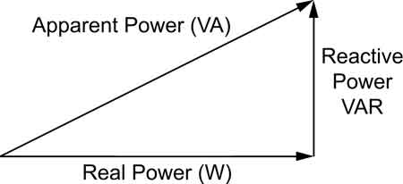
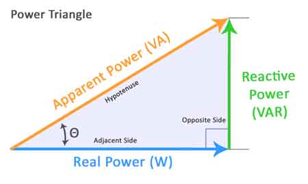
In AC systems, electrical energy is made up of three interrelated components: kW, kVAR, and kVa. These are best understood using the power triangle, a visual representation of the relationship between these values in a right-angled triangle.
-
Real power (kW) is the usable energy that performs actual work in a system.
-
Reactive power (kVAR) is the non-working energy that sustains electric and magnetic fields.
-
Apparent power (kVA) is the total energy supplied, combining both real and reactive components.
Mathematically, this relationship is expressed as a form of complex power:
Where:
-
S = Apparent power
-
P = Real power
-
Q = Reactive power
The angle between the real and S vectors is known as the phase angle (φ). The cosine of this angle (cos φ) gives us the PF, a key metric for evaluating electrical efficiency. A low PF indicates that more Q is present, resulting in increased losses and larger equipment sizing requirements.
Comparison of P, Q and S
| Type of Power | Symbol | Unit | Description | Function in AC Systems |
|---|---|---|---|---|
| Real P | P | kW (kilowatts) | The actual energy that performs useful work (e.g., lighting, motors) | Loads measured by wattmeters |
| Reactive P | Q | kVAR (kilovolt-amperes reactive) | Power that sustains electric and magnetic fields but does no useful work | Causes current to circulate; affects PF |
| Apparent P | S | kVA (kilovolt-amperes) | The vector sum of real and Q | Total energy supplied; determines equipment sizing |
| PF | PF | — | Ratio of real power to apparent power (PF = cos φ) | Indicates efficiency of energy use; should be as close to 1 as possible |
| Phase Angle | φ | Degrees | The angle between voltage and current waveforms | Affects the PF; caused by inductive or capacitive loads |
Practical Examples and Analogies
Understanding real, reactive, and S can be challenging without a tangible frame of reference. One of the most effective analogies is the beer mug analogy, which helps visualize the differences:
Imagine pouring a beer into a glass.
-
The beer itself represents real power (kW)—this is the usable energy that actually does work, such as running a motor or lighting a lamp.
-
The foam that forms on top symbolizes reactive power (kVAR)—it doesn’t do useful work but still takes up space in the system.
-
The total contents of the glass, beer plus foam, represent apparent power (kVA)—the total energy delivered to the system.
Just as only the beer quenches your thirst, only P delivers usable energy. But the foam still occupies part of the glass, just as Q affects the overall capacity and efficiency of an electrical system.
For electricians, this concept becomes practical when designing or troubleshooting AC systems. For example, a large industrial motor may draw substantial Q, which reduces the system’s PF and necessitates the use of capacitor banks to offset these inefficiencies. Understanding the distinction helps ensure proper equipment sizing, voltage regulation, and energy cost control.
Power Factor
PF is a critical measure in AC circuits, indicating how effectively electrical energy is utilized. It represents the ratio of real power to S. RP is the portion that performs actual work, like running motors or lighting. AP encompasses both RP and RP, the latter being necessary for some electrical equipment but not contributing to useful work. A higher PF signifies a larger portion of the total energy used effectively, leading to greater efficiency and cost savings. Discover how to enhance system performance by utilizing power factor correction capacitors, which minimize Q and enhance overall PQ.
FREE EF Electrical Training Catalog
Download our FREE Electrical Training Catalog and explore a full range of expert-led electrical training courses.

- Live online and in-person courses available
- Real-time instruction with Q&A from industry experts
- Flexible scheduling for your convenience
Measuring PF
PF is a crucial measure of how effectively electrical energy is being converted into useful work. It is calculated as the cos φ, or the cosine of the phase angle between current and voltage in an AC circuit. The PF ranges from 0 to 1:
-
A PF of 1 means all energy is being used for work—ideal efficiency.
-
A low PF indicates a higher proportion of Q, resulting in energy waste and the need for larger electrical infrastructure.
Monitoring and improving PF is essential in industrial environments where large inductive loads (like motors) are common. Techniques such as PF correction—typically by installing capacitor banks—can reduce kVAR demand, improve voltage regulation, and minimize utility penalties for inefficient energy use.
Understanding how to measure and correct PF allows electricians to optimize system performance using the principles of the power triangle and complex systems.
Apparent Power (S)
In AC circuits, S represents the total energy delivered. This value combines RP, which is responsible for performing work, and RP, which is associated with energy storage and release in inductive and capacitive components. S is vital as it determines the total current flowing, which in turn influences the sizing of electrical equipment, such as wires, transformers, and circuit breakers. Understanding this concept ensures the safe and efficient operation of electrical systems. You can simplify efficiency calculations by using our apparent power calculator to determine the total kVA load in your system.
AC Circuits
Real and RP are phenomena specific to AC circuits, where voltage and current alternate direction periodically. This alternating nature gives rise to RP, caused by energy storage in inductors and capacitors. These components store energy during one part of the AC cycle and release it back into the circuit during another, creating a back-and-forth flow of energy that constitutes RP.
Inductance and Capacitance
Inductance and capacitance are fundamental properties of electrical components that significantly influence AC circuit behaviour. Inductors, like coils and transformers, store energy in magnetic fields, while capacitors store energy in electric fields. When present in an AC circuit, they cause a phase shift between voltage and current, leading to the generation of RP.
Power Triangle
The triangle visually represents the relationship between real, reactive, and AP in an AC circuit. In this right-angled triangle, P is the adjacent side, RP the opposite side, and S the hypotenuse. The angle between the real and AP is the PF angle. This triangle provides a clear way to understand the interplay between these different forms of electrical energy. Accurate load balancing begins with understanding the basics of three-phase power calculation to ensure efficient energy distribution in industrial systems.
kW and kVAR
P is measured in watts (W) or kilowatts (kW), while P is measured in volt-amperes reactive (VAR) or kilovars (kVAR). These units reflect their distinct nature. It represents the rate of energy consumption and conversion into useful work, while P represents the rate of energy storage and release without performing work.
Power Factor Correction
PF correction improves an electrical system's PF by reducing P. This is typically achieved by adding capacitors to offset the inductive reactance of loads, such as motors and transformers. Improving the PF reduces energy waste, lowers electricity bills, and improves system efficiency. Improving system efficiency and reducing utility charges starts with effective power factor correction to minimize wasted Q.
Efficiency
P is the amount of energy that performs useful work in an electrical system, consumed by loads to produce light, heat, motion, or other desired effects. RP, though necessary for some equipment, doesn't contribute to useful work. Instead, it represents energy stored and released by inductive and capacitive components. Minimizing RP through PF correction improves the overall efficiency of the electrical system. Our article on motor power factor explores how inductive motors affect energy efficiency and how automatic correction devices can help.
Harmonics
Harmonics are distortions in the electrical current waveform that can cause problems. They are multiples of the fundamental frequency of the AC supply, generated by nonlinear loads such as electronic devices and variable-speed drives. Harmonics can increase resistance, leading to a reduced PF and increased energy losses.
Harmonic distortion can severely impact system reliability and efficiency, as explained in our in-depth guide on power quality and harmonics.
Related Articles


