Electricity and Electrical Energy


Electricity powers modern engineering, driving circuits, voltage, current, and AC/DC power systems for transmission, distribution, and control. Engineers analyze resistance, impedance, and frequency, optimize grids, and integrate renewables with transformers, generators, and smart controls.


What Is Electricity?

Electricity is the flow of charge enabling energy conversion, signal transmission, and power control across circuits.

✅ Quantified by voltage (V), current (A), and power (W)

✅ Governed by Ohm's Law, Kirchhoff's Laws, and Maxwell's equations

✅ Transmitted via grids using AC, transformers, and protection


Electricity is a manufactured product. It is not something you pump out of the ground or mine or collect from the sun or wind. For a clear primer on definitions and units, visit what electricity is to ground these ideas.

Electric power is manufactured from a rotating machine that we call an electrical generator. After it is generated, (manufactured) it is then delivered through copper wires to where it is utilized If you want to see how turbines and alternators convert motion into power, explore the electricity generator to understand key components and operation.

Electricity - most people don't understand what it is. They just turn on the light switch or start the appliance or push the button and something works. It's only when there is no electric power available that we start to consider the importance of it in our daily personal and working lives. A step-by-step explanation of fields, voltage, and current is outlined at how electricity works for readers new to the topic.

But the invention of the machine to generate power is right next to the invention of the printing press in the list of major contributions to the advancement of human civilization. For context on pioneers from Faraday to Tesla, review who invented electricity to connect invention with modern grids.

Without it, we would be burning wood and coal to heat our homes and businesses and using oil and candles to light our way in the dark. That is the way it was for humans civilization for countless centuries. Only since the invention of the electric generator have humans been able to advance in every aspect of modern life. In fact, modern living is defined by electric power. This shift from fuels to electrons is traced in the history of electricity to show how infrastructure reshaped society.

We have assembled a series of pages in our web site to help you to understand the business of electricity - how it works and how it is used. To dive deeper into fundamentals before the business aspects, start with electricity: how it works for a concise technical overview.

We hope that you can use this information to better understand the technology and issues behind the manufacturing of electric power. Further reading on thermal, hydro, and renewable pathways is available at how electricity is generated to see how manufacturing methods compare.


Related Articles

Related News

Equivalent Resistance

Equivalent resistance is the total resistance of a circuit that simplifies multiple resistors into a single resistor. It is calculated differently for series and parallel circuits, helping determine current flow, voltage distribution, and overall power consumption in electrical networks.


What is Equivalent Resistance?

Equivalent resistance is a crucial concept for individuals working with electrical circuits. It: 

✅ Represents the single resistance that replaces multiple resistors in a circuit.

✅ Simplifies calculations of current, voltage, and power.

✅ Found using series or parallel formulas based on resistor arrangement.

By mastering the calculation methods for series and parallel circuits, understanding the relationship with Ohm's law, and applying Kirchhoff's laws in more complex situations, you can efficiently analyze and design electrical systems that meet the requirements of various applications. Furthermore, by incorporating equivalent resistance calculations into your skillset, you'll be better prepared to tackle the exciting challenges presented by the ever-evolving world of electronics and power systems.


Equivalent Resistance in Series vs. Parallel Circuits

Configuration Formula Key Characteristics Example Calculation
Series R_eq = R1 + R2 + R3... Same current flows through all resistors; total resistance increases; voltage drop varies across components. For R1=4Ω, R2=6Ω: R_eq = 4Ω + 6Ω = 10Ω
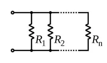
Parallel 1/R_eq = 1/R1 + 1/R2 + 1/R3... Same voltage across each resistor; total resistance decreases; current divides among paths. For R1=4Ω, R2=6Ω: 1/R_eq = 1/4 + 1/6 = 0.416 → R_eq ≈ 2.4Ω

To calculate the equivalent resistance of a network, it is often necessary to determine the sum of the individual resistances. This involves adding the resistance values of each individual resistor in the network, providing a baseline for further calculations. This is a resistance formula for a single resistor, as well as for calculating resistors connected in parallel or in series.

Electrical resistance (R) is a measure of the opposition to the flow of electric current within a circuit. It is determined by the material and dimensions of the conductor, as well as the temperature and other environmental factors. It is measured in ohms (Ω), with lower R indicating greater conductivity and vice versa.


Equivalent Resistance Formula

When a group of resistors is connected end-to-end, they form a series. In a series circuit, the total resistance is equal to the sum of the individual Rs, as current must flow through each resistor in turn. The equivalent resistance of a series circuit is calculated by adding the values of each individual resistor:

Req = R1 + R2 + R3 + ...

Resistors connected across the same potential difference, or applied voltage, are referred to as being connected in parallel. In a parallel circuit, the total R is less than the R of any individual resistor as the current divides among the resistors. The equivalent resistance of a parallel circuit is calculated using the reciprocal formula:

1/Req = 1/R1 + 1/R2 + 1/R3 + ...

Equivalent resistance is the single R value that can replace a group of resistors in a circuit, offering the same overall R. This simplifies circuit analysis and allows for more straightforward calculations of current and voltage values.

Ohm's law is an essential principle in electronics and relates closely to equivalent resistance. Ohm's law states that the current (I) flowing through a resistor is directly proportional to the applied voltage (V) and inversely proportional to the R. The equation is:

V = IR

By calculating equivalent resistance for a given circuit, we can use Ohm's law to determine the overall current flowing through the circuit and the voltage drops across each resistor.


Series and parallel circuits exhibit different properties when it comes to equivalent resistance. In series circuits, the overall R increases with the addition of more resistors, which means the total current will decrease. In parallel circuits, adding more resistors results in a decrease in total resistance, causing an increase in total current. Understanding these differences is crucial for designing circuits that meet specific electrical requirements.


Kirchhoff's Law

Kirchhoff's laws are another essential tool for calculating equivalent resistance in more complex circuits that cannot be simplified as purely series or parallel. Kirchhoff's current law (KCL) states that the sum of currents entering a junction in a circuit must equal the sum of currents leaving the junction. Kirchhoff's voltage law (KVL) asserts that the sum of the voltages around any closed loop in a circuit must equal zero. By applying these laws, we can create a system of equations to solve for unknown resistance values in a network, ultimately determining the equivalent resistance.


Real-World Applications

Real-world applications of equivalent resistance can be found in various fields, such as electronics, power distribution, and telecommunications. For example, various components have different R values in electronic devices, such as smartphones. Calculating the equivalent resistance enables engineers to design efficient power management systems, ensuring optimal performance and extended battery life. In power distribution networks, equivalent resistance calculations are essential for determining voltage drops and current values across transmission lines, enabling the design of efficient and reliable power delivery systems.

Understanding equivalent resistance is vital for professionals and students who deal with electrical circuits. From simplifying complex networks to designing efficient circuits, equivalent resistance plays a central role in analyzing and developing modern electronic systems. Familiarity with this concept and associated principles like Ohm's law and Kirchhoff's laws ensures a strong foundation for anyone working with electronics, power systems, and telecommunications.


Technology Advances

As technology advances, the importance of equivalent resistance in designing and analyzing new devices and systems will only grow. Calculating and understanding equivalent resistance enables engineers to push the boundaries of innovation and improve upon existing systems, resulting in more efficient, high-performance solutions for consumers and industries alike.

To further develop your understanding of equivalent resistance and related concepts, consider exploring the wealth of educational resources available online and in textbooks, as well as seeking hands-on experience through workshops or real-world projects. Applying this knowledge to practical scenarios will enable you to tackle various electrical and electronic challenges.

Related Articles


View more

Prospective Fault Current Meaning Explained

Prospective fault current (PFC) is the highest electric current that can flow in a system during a short circuit. It helps determine equipment ratings, breaker capacity, and safety measures in electrical installations to prevent overheating, fire, or component failure.


What is the Meaning of Prospective Fault Current?

Prospective fault current refers to the maximum current expected during a short circuit at any point in an electrical system.

✅ Helps size circuit breakers and fuses for safe disconnection

✅ Ensures compliance with installation and safety codes

✅ Prevents equipment damage from excessive short-circuit current

Prospective fault current (PFC) is a key factor in the safety and design of electrical systems. It represents the maximum current that could flow in the event of a fault, such as a short circuit. Understanding PFC is essential for selecting protective devices that can handle fault conditions safely. This article explores what PFC is, how it is measured, and its importance for electrical installations, while addressing key questions. Understanding electrical short circuits is key to calculating prospective fault current and ensuring system safety.

When measuring prospective short circuit current in an electrical system, it’s essential to perform tests between L1 N CPC and L2 N CPC to assess the fault current across different phases and protective conductors. These measurements help identify the maximum prospective fault current present in the system, especially at points involving live conductors. Whether taking note of a single-phase supply or between line conductors on a three-phase supply, proper testing protocols must be followed. Technicians should always use insulated test leads rated for the expected voltage and current levels, and please refer to the test meter manufacturer’s instruction for safe and accurate operation. Reliable results ensure that the protective devices can safely interrupt fault conditions, preventing system damage and ensuring compliance with fault current protection standards.


Frequently Asked Questions

Why is it Important?

Prospective fault current refers to the maximum current that could pass through a system during a fault. The PFC helps determine the breaking capacity of fuses and circuit breakers, ensuring these protective devices can handle high currents safely. This is vital for protecting the electrical installation and those working near it.

Understanding PFC is critical for ensuring increased safety for employees and third parties. Protective devices must be selected to handle PFC; otherwise, they may fail to operate correctly, leading to severe consequences, such as fires or injuries. To fully grasp how PFC affects energy flow, it’s useful to review the concept of electrical resistance in a circuit.


How is Prospective Fault Current Measured or Calculated?

PFC can be measured or calculated using tools such as a multifunction tester, often during fault current testing. The instrument uses a single-phase supply or between line conductors on a three-phase supply to measure the maximum potential current at various points in the installation. Testing often involves checking currents between L1 N CPC, L2 N CPC, and L3 N CPC, which measure current between the lines to neutral in a three-phase system.

When performing these tests, technicians should follow regulation 612.11 of a single-phase supply or between line conductors on a three-phase supply, ensuring that simple and circuit protective conductors are all connected correctly. Accurate testing must also account for maximum current flow. Live testing requires extreme caution, and it is important to refer to the test meter manufacturer’s instructions to ensure proper usage and safety. In three-phase systems, 3-phase electricity significantly impacts how fault current behaves during a short circuit.


What is the difference between PFC and Short-Circuit Current?

Though often confused, prospective fault current and short-circuit current are distinct. Prospective fault current is the theoretical maximum current that could flow in a fault, used to predict the worst-case scenario for selecting protective devices. Short-circuit current refers to the actual current that flows during a fault, which depends on real-time conditions such as circuit impedance. Prospective fault current is one of the many concepts that form the foundation of electricity fundamentals.


How Does Prospective Fault Current Impact the Selection of Protective Devices?

The calculation of PFC plays a critical role in selecting the correct protective devices. Circuit breakers and fuses must have a breaking capacity that matches or exceeds the prospective fault current in the system. If the PFC exceeds the breaking capacity, the protective device may fail, leading to dangerous electrical hazards.

For instance, fault current testing using a multifunction tester between phases and neutral (L1, L2, L3) ensures that protective devices are rated to handle the highest potential fault current in the system. Proper circuit protection ensures that the system can interrupt faults safely, minimizing the risks to workers and equipment.


What Standards and Regulations Govern Prospective Fault Current Calculations?

Various standards, such as IEC 60909, govern how PFC is calculated and how protective devices are selected. These regulations ensure that electrical systems are designed to handle maximum fault conditions safely. Regulation 612.11 further specifies how live testing should be conducted using proper equipment and safety protocols.

It is essential to test PFC at relevant points in the system and follow testing standards to ensure compliance and safety. Devices selected based on PFC calculations help ensure that electrical systems can withstand faults and maintain reliable operation.

Prospective fault current is a crucial element in the safety and reliability of electrical installations. By calculating PFC, engineers can select protective devices that ensure safe operation in the event of a fault. Testing for fault currents at different points in the system and adhering to regulations are essential steps in preventing hazardous conditions.

By choosing protective devices with the appropriate breaking capacity and following safe testing practices, electrical installations can handle fault conditions and protect both workers and equipment from harm. Selecting protective devices that match the PFC is essential for reliable electric power systems design.


Related Articles


View more

3 PHASE ELECTRICITY

3 Phase Electricity supplies AC three-phase power via 120° phase-shifted sinusoidal waveforms, enabling balanced loads, higher power factor, efficient distribution, and smooth torque for industrial motors across commercial facilities and the electrical grid.


What Is 3 Phase Electricity?

An AC system with three sinusoidal phases delivering balanced, efficient power for distribution and industrial motors.

✅ Three 120° phase-shifted AC waveforms share balanced loads.

✅ Lower conductor size and losses than single-phase systems.

✅ Powers large motors with smoother torque and better efficiency.


3 phase electricity is referred to alternating current. It is best described as the timing of the electron movements. It is the most common delivery method worldwide because it is a cheaper and easier way to transmit power from one place to another. While this method of electrical transmission is popular in industrial, commercial and institutional power systems, most homes only use single-phase power. For a concise overview, see the three-phase electricity guide for context.


What does it mean?

If wires are in "phase", it means that timing of the electron movement, back and forth, is the same. The electrons are "in step" or "in time".

For newcomers, the basic electricity tutorial explains charge, current, and phase in simple terms.

To transmit and distribute alternating current, it is more efficient to use 3 circuits that are out of sequence. This idea was discovered by Nikola Tesla (1856 -1943). Much of its efficiency is because there is always voltage (electrons moving) in at least one wire.

You can review how alternating current behaves in circuits in the how electricity works resource to see why shifting phases improves continuity.

He found that it is an arrangement that fits in very nicely with generator design. The 120° phasing separation allows close to the optimum spacing and size of the copper conductors around the stator bore. The compatible generator is the cheapest form to make. Design notes for 3-phase power highlight how 120° spacing reduces copper and iron losses.

This type of power is designed especially for large electrical loads where the total electrical load is divided among the three separate phasing sequences. As a result, the wire and transformers will be less expensive than if these large loads were carried on a single system.

Generators usually have three separate windings, each producing its own separate single-phase voltage. Since these windings are staggered around the generator circumference, each of the voltages is "out of phase" with one another. That is, each of the three reaches the maximum and minimum points in the AC cycle at different times.

Definitions of "phase angle" and "phase sequence" are covered in the electricity terms glossary for reference.

Power is generated at electric utilities in this way. But, if this power is better than single phase, why not four, five or six phase? Theoretically, these would be even better, but equipment manufacturers would have to build motors to use it, and that just wouldn't be cost effective given the installed base of equipment that must continue to be powered. Utility practices for distribution are summarized in the electricity supply overview which also outlines standard voltage systems.

The word is often abbreviated using the Greek letter "phi" and is written as a zero with a slash mark through it.

The most important class of load is the electric motor. An induction motor has a simple design, inherently high starting torque, and high efficiency. Such motors are applied in industry for pumps, fans, blowers, compressors, conveyor drives, and many other kinds of motor-driven equipment. A motor will be more compact and less costly than a motor of the same voltage class and rating; and AC motors above 10 HP (7.5 kW) are uncommon. Three phase motors will also vibrate less and hence last longer than motor of the same power used under the same conditions.

Large air conditioning, etc. equipment use motors for reasons of efficiency, economy and longevity.

Resistance heating loads such as electric boilers or space heating may be connected to systems. Electric lighting may also be similarly connected. These types of loads do not require the revolving magnetic field characteristic of motors but take advantage of the higher voltage and power level usually associated with distribution. Fluorescent lighting systems also benefit from reduced flicker if adjacent fixtures are powered from different.

Large rectifier systems may have inputs; the resulting DC current is easier to filter (smooth) than the output of a rectifier. Such rectifiers may be used for battery charging, electrolysis processes such as aluminum production, or for operation of DC motors.

An interesting example of a load is the electric arc furnace used in steelmaking and in refining of ores.

In much of Europe stoves are designed to allow for a feed. Usually the individual heating units are connected between phase and neutral to allow for connection to a supply where this is all that is available.

For homeowners, the home electricity section explains single-phase panels, breakers, and typical loads.


Related Articles

View more

Ohm's Law Formula

The Ohm's Law formula is a cornerstone of electrical engineering, serving as a basis for analyzing and designing electric circuits. Its applications range from determining the appropriate values of electrical components to predicting the behaviour of complex systems. By exploring the relationship between voltage, current, and resistance and their connections with other fundamental laws in electromagnetism, we can gain a deeper understanding of the principles that govern the flow of electricity and its conversion into other forms of energy.

Ohm's Law states that the relationship between voltage, current, and resistance. This law, named after its discoverer Georg Simon Ohm, has wide-ranging applications in various fields, from the design of simple electrical circuits to complex electronic systems.

Ohm's Law, denoted as V=IR, dictates that the voltage (V) across a conductor between two points is directly proportional to the current (I) flowing through it, as long as the resistance (R) of the material remains constant. This equation lays the foundation for understanding electric circuits, and its relevance extends to both alternating current (AC) and direct current (DC) systems.

Let's consider a simple scenario to implement Ohm's Law. In an electrical circuit, a battery supplies voltage (also called electric potential or electromotive force), which causes electrons to flow, generating an electric current. The flow of these electrons encounters resistance due to the physical properties of the materials used in the circuit. The higher the resistance, the more the material opposes the flow of electrons, leading to a decrease in the electric current.

A practical application of Ohm's Law calculator can be found in determining a resistor's suitable value for a circuit. Using the formula V=IR, you can calculate the required resistance by rearranging the equation as R=V/I, where you substitute the known voltage and current values to find the unknown resistance.

When it comes to units, voltage is measured in volts (V), current in amperes (A), and resistance in ohms (Ω). It is essential to be mindful of these units when working with electrical components, as they determine the overall performance and safety of the system.

While Ohm's Law plays a critical role in understanding electric circuits, it is also interconnected with the concept of conductivity. Conductivity, a measure of a material's ability to conduct electrical energy, is the reciprocal of resistance. The more conductive a material is, the less resistance it exhibits, and vice versa. Conductivity helps engineers and designers select the right materials for specific applications, ensuring the efficiency and reliability of electrical systems.

However, Ohm's Law has its limitations. In real-world scenarios, resistance may not remain constant for all materials and under all conditions. Factors such as temperature, pressure, and the material's non-linear behaviour can cause deviations from the ideal behaviour predicted by Ohm's Law. As a result, this law is considered an ideal approximation for most practical purposes but may not be universally applicable.

Ohm's Law is also related to other fundamental laws in electromagnetism, such as Faraday's, Lenz's, and Biot-Savart's law. Faraday's Law describes the induction of voltage in a conductor moving through a magnetic field, while Lenz's Law explains the direction of the induced current due to this magnetic field. The Biot-Savart Law, on the other hand, calculates the magnetic field generated by an electric current. Understanding these laws is vital for grasping more complex concepts and phenomena in electromagnetism and their practical applications.


How to use Ohm's Law Equation

Let's consider an example of how to use Ohm's Law in a practical situation.

Suppose you have a 12-volt (V) battery connected to a simple electrical circuit with a single resistor. The current flowing through the resistor is measured to be 2 amperes (A). You can use Ohm's Law to calculate the resistance of the resistor in the circuit.

Recall the Ohm's Law formula: V = IR, where V is voltage, I is current, and R is resistance.

In this example, we know the voltage (V = 12 V) and the current (I = 2 A), and we want to find the resistance (R).

Rearrange the formula to solve for resistance: R = V / I

Now, substitute the known values into the formula:

R = 12 V / 2 A

R = 6 ohms (Ω)

So, the resistance of the resistor in this circuit is 6 ohms. By using Ohm's Law, you can determine unknown values in a circuit, such as resistance, as long as you have the other two known values (voltage and current).

View more

Capacitors Explained

Capacitors store electrical energy via a dielectric, offering capacitance for filtering, smoothing, and decoupling in AC/DC circuits, RC networks, and power supplies, spanning ceramic, film, and electrolytic types with distinct impedance profiles.


What Are Capacitors?

Capacitors store charge using a dielectric, providing capacitance for filtering, timing, and decoupling in circuits.

✅ Types: ceramic, film, tantalum, electrolytic; surface-mount or through-hole

✅ Functions: decoupling, bulk energy storage, timing, AC coupling

✅ Key specs: capacitance, voltage rating, ESR/ESL, tolerance, ripple


Capacitors for Power Factor Correction

It is desirable to add shunt capacitors in the load area to supply the lagging component of current with a positive negative charging electrons. The cost is frequently justified by the value of circuit and substation capacity released and/or reduction in losses. Installed cost of shunt capacitors is usually least on primary distribution systems and in distribution substations. For foundational context, see what a capacitor is to understand reactive power roles.

The application of shunt capacitors to a distribution feeder produces a uniform voltage boost per unit of length of line, out to its point of application. Therefore, it should be located as far out on the distribution system as practical, close to the loads requiring the kilovars. There are some cases, particularly in underground distribution, where secondary capacitors are economically justified despite their higher cost per kilovar. The placement effectiveness also depends on capacitance characteristics relative to feeder impedance.

Development of low-cost switching equipment for capacitors has made it possible to correct the power factor to a high value during peak-load conditions without overcorrection during light-load periods. This makes it possible for switched capacitors to be used for supplementary voltage control. Time clocks, temperature, electric charge voltage, current flows, and kilovar controls are common actuators for high frequency capacitor switching. Utilities typically choose among several types of capacitors to balance switching duty and reliability.

Capacitor Installations

Capacitors for primary systems are available in 50- to 300-kvar single phase units suitable for pole mounting in banks of 3 to 12 units. Capacitors should be connected to the system through fuses so that a capacitor failure will not jeopardize system reliability or result in violent case rupture. When voltage ratings limit a single unit, engineers connect capacitors in series to distribute stress effectively.


Effect of Shunt Capacitors on Voltage

Proposed permanently connected capacitor applications should be checked to make sure that the voltage to some customers will not rise too high during light-load periods. Switched capacitor applications should be checked to determine that switching the capacitor bank on or off will not cause objectionable flicker in electronics. Selecting appropriate sizes in the standard unit of capacitance helps manage voltage rise and flicker.


Effect of Shunt Capacitors on Losses

The maximum loss reduction on a feeder with distributed load is obtained by locating positively negatively capacitor banks on the feeder where the capacitor kilovars is equal to twice the load kilovars beyond the point of installation. This principle holds whether one or more than one capacitor bank is applied to a feeder. To meet kvar targets with modular banks, utilities often add capacitance in parallel so reactive output scales predictably.

Capacitor kilovars up to 70% of the total kiovar load on the feeder can be applied as one bank with little sacrifice in the maximum feeder-loss discharge reduction possible with several capacitor banks.

A rule of thumb for locating a single capacitor bank on a feeder with uniformly distributed loads is that the maximum loss reduction can be obtained when the capacitor kilovars of the bank is equal to two-thirds of the kilovar load on the feeder. This bank should be located two-thirds of the distance out on the distributed feeder portion for object charging. Deviation of the capacitor bank location from the point of maximum loss reduction by as much as 10 per cent of the total feeder length does not appreciably affect the loss benefit. Therefore, in practice, in order to make the most out of the capacitor's loss reduction and voltage benefits, it is best to apply the capacitor bank just beyond the optimum loss-reduction location.

Batteries and capacitors seem similar as they both store and release electrical energy. However, there are crucial differences between them that impact their potential electronic applications due to how they function differently, depending on insulator material.


Supercapacitors

A capacitor battery aligns the molecules of a dielectric across an electric field to store energy. A supercapacitor aligns the charging of an electrolyte on either side of an insulator to store a double-layer charge.

Electrolytic capacitors consist of two or more conductive capacitors plate, separated by a dielectric. When an electric current enters the capacitor, the dielectric stops the flow and a charge builds up and is stored in an electric field between the metallic plates. Each capacitor is designed to have a particular capacitance (energy storage). When a capacitor is connected to an external circuit, a current will rapidly discharge. Plate area, separation, and dielectric constant together determine capacitance and thus energy density.

In a supercapacitor, there is no dielectric between conducting plates; rather, there is an electrolyte and a thin insulator such as cardboard or paper. When a current is introduced to the supercapacitor, ions build on either side of the insulator to generate a double layer of charge, no matter the capacitor charged. Supercapacitors are limited to low voltages, but very high capacitance frequencies, as a high voltage would break down the electrolyte. 


Batteries

There are different types of capacitor batteries, which detemine the capacitance of a capacitor. Different battery types are distinguished by their chemical makeup. The chemical unit, called the cell, contains three main parts; a positive terminal called the cathode, negative terminal called the anode, and the electrolyte. Batteries store electric energy. The battery charges and discharges through a chemical reaction that generates a voltage. The store of charge in the battery is able to provide a consistent DC voltage. In rechargeable batteries, the chemical energy that is converted into electricity can be reversed using an outside electrical energy to restore the charge of capacitors storing power in the batteries.


Related Articles

View more

Electricity and Magnetism - Power Explained

Electricity and magnetism are interconnected forces forming electromagnetism, which explains electric currents, magnetic fields, and their interactions. These principles power motors, generators, transformers, and more in modern electrical and magnetic systems.


What is: "Electricity and Magnetism"

Electricity and magnetism are fundamental forces in physics that form the basis of electromagnetism.

✅ Describe how electric charges and magnetic fields interact in nature and technology

✅ Underlie the function of motors, transformers, and generators

✅ Explain current flow, induction, and electromagnetic waves

Electricity - What is it?

Electricity is a form of energy that is transmitted through copper conductor wire to power the operation of electrical machines and devices, including industrial, commercial, institutional, and residential lighting, electric motors, electrical transformers, communications networks, home appliances, and electronics.

When charged particles flow through the conductor, we call it "current electricity". This is because when the charged particles flow through wires, electricity also flows. We know that current means the flow of anything in a particular direction. For example, the flow of water. Similarly, the flow of electricity in a specific direction is referred to as an electric current. The interplay of charge, field, and force is explored in what is electric load, covering how power is delivered in electromagnetic systems.

When an electric current flows, it produces a magnetic field, a concept closely tied to Faraday's Law of Induction, which underpins much of modern electrical engineering.


Magnetism  - What is it?

Magnetism is a type of attractive or repulsive force that acts up to certain distance at the speed of light. The distance up to which this attractive or repulsive force acts is called a "magnetic field". Magnetism is caused by the moving electric charges (especially electrons). When two magnetic materials are placed close to each other, they experience an attractive or repulsive force. To understand magnetic field strength and units, our magnetic induction basics in induction page discusses flux and Teslas.


What is the relationship between electricity and magnetism?

In the early days, scientists believed that there were two uniquely separate forces. However, James Clerk Maxwell proved that these two separate forces were actually interrelated.

In 1820, Hans Christian Ørsted observed a surprising phenomenon: when he switched on the battery from which the electric current was flowing, the compass needle moved away from the north pole. After this experiment, he concluded that the electric current flowing through the wire produces a magnetic field.

Electricity and magnetism are closely related to each other. The electric current flowing through the wire produces a circular magnetic field outside the wire. The direction (clockwise or counterclockwise) of this magnetic field depends on the direction of the electric current.

Similarly, a changing magnetic field generates an electric current in a wire or conductor. The relationship between them is called electromagnetism.

Electricity and magnetism are interesting aspects of electrical sciences. We are familiar with the phenomenon of static cling in our everyday lives - when two objects, such as a piece of Saran wrap and a wool sweater, are rubbed together, they cling.

One feature of this that we don't encounter too often is static "repulsion" - if each piece of Saran wrap is rubbed on the wool sweater, then the pieces of Saran wrap will repel when brought near each other. These phenomena are interpreted in terms of the objects acquiring an electric charge, which has the following features:

  • There are two types of charge, which by convention are labelled positive and negative.

  • Like charges repel, and unlike charges attract.

  • All objects may have a charge equal to an integral number of a basic unit of charge.

  • Charge is never created or destroyed.

To explore how electric and magnetic forces interact at a distance, see what is static electricityis, which includes examples like static cling and repulsion.


Electric Fields

A convenient concept for describing these electric current and magnetic current forces is that of electric field currents. Imagine that we have a fixed distribution of charges, such as on the plate below, and bring a test charge Q into the vicinity of this distribution.


img134 
 

Fig. 1 Test charge in the presence of a fixed charge distribution

This charge will experience a force due to the presence of the other charges. One defines the electric field of the charge distribution as:


img135

The electric field is a property of this fixed charge distribution; the force on a different charge Q' at the same point would be given by the product of the charge Q' and the same electric field. Note that the electric field at Q is always in the same direction as the electric force.

Because the force on a charge depends on the magnitude of the charges involved and the distances separating them, the electric field varies from point to point, both in magnitude and direction.

By convention, the direction of the electric field at a point is the direction of the force on a positive test charge placed at that point. An example of the electric field due to a positive point charge is given below. 


img136

Fig. 2: Electric field lines of a positive charge


Power and Magnetic Fields

A phenomenon apparently unrelated to power is electromagnetic fields. We are familiar with these forces through the interaction of compasses with the Earth's magnetic field, or the use of fridge magnets or magnets on children's toys. Magnetic forces are explained in terms very similar to those used for electric forces:

  • There are two types of magnetic poles, conventionally called North and South
  • Like poles repel, and opposite poles attract

However, this attraction differs from electric power in one important aspect:

  • Unlike electric charges, magnetic poles always occur in North-South pairs; there are no magnetic monopoles.

Later on we will see at the atomic level why this is so.

As in the case of electric charges, it is convenient to introduce the concept of a magnetic field in describing the action of magnetic forces. Magnetic field lines for a bar magnet are pictured below.

img137
 

Fig. 3: Magnetic field lines of a bar magnet

One can interpret these lines as indicating the direction that a compass needle will point if placed at that position.

The strength of magnetic fields is measured in units of Teslas (T). One tesla is actually a relatively strong field - the earth's magnetic field is of the order of 0.0001 T.


Magnetic Forces On Moving Charges

One basic feature is that, in the vicinity of a magnetic field, a moving charge will experience a force. Interestingly, the force on the charged particle is always perpendicular to the direction it is moving. Thus, magnetic forces cause charged particles to change their direction of motion, but they do not change the speed of the particle.

This property is utilized in high-energy particle accelerators to focus beams of particles, which ultimately collide with targets to produce new particles, including gamma rays and radio waves.

Another way to understand these forces of electricity and magnetism is to realize that if the force is perpendicular to the motion, then no work is done. Hence, these forces do no work on charged particles and cannot increase their kinetic energy.

If a charged particle moves through a constant magnetic field, its speed stays the same, but its direction is constantly changing. A device that utilizes this property is the mass spectrometer, which is used to identify elements. A basic mass spectrometer is pictured below.


img145
 

Figure 4: Mass spectrometer

In this device, a beam of charged particles (ions) enters a region of a magnetic field, where they experience a force and are bent in a circular path. The amount of bending depends on the mass (and charge) of the particle, and by measuring this amount one can infer the type of particle that is present by comparing it to the bending of known elements.


Magnet Power From Electric Power

A connection was discovered (accidentally) by Orsted over 100 years ago, when he noticed that a compass needle is deflected when brought into the vicinity of a current-carrying wire. Thus, currents induce magnetic fields in their vicinity. An electromagnet is simply a coil of wires which, when a current is passed through, generates a magnetic field, as below.


img149
 

Figure 5: Electromagnet

Another example is in an atom, where an electron is a charge that moves around the nucleus. In effect, it forms a current loop, and hence, a magnetic field may be associated with an individual atom. It is this basic property which is believed to be the origin of the magnetic properties of various types of materials found in nature.

Maxwell's equations (also known as Maxwell's theory) are a set of coupled partial differential equations that, together with the Lorentz force law, form the foundation of classical electromagnetism, which deals with electromagnetic radiation, electromagnetic waves, and electromagnetic force.  For a deeper understanding of the magnetic effects of electrical current, our article on electromagnetic induction explains how magnetic fields can generate electricity in conductors.


Related Articles


View more

Sign Up for Electricity Forum’s Newsletter

Stay informed with our FREE Newsletter — get the latest news, breakthrough technologies, and expert insights, delivered straight to your inbox.

Electricity Today T&D Magazine Subscribe for FREE

Stay informed with the latest T&D policies and technologies.
  • Timely insights from industry experts
  • Practical solutions T&D engineers
  • Free access to every issue

Download the 2025 Electrical Training Catalog

Explore 50+ live, expert-led electrical training courses –

  • Interactive
  • Flexible
  • CEU-cerified