Electricity Safety Explained
By R.W. Hurst, Editor
Electricity safety protects workers, electricians, employers, and homeowners from shock, arc flash, burns, fire, and explosion hazards through grounding, PPE, lockout tagout, risk assessment, training, and electrical safety standards.
Understanding Electricity Safety
Electricity safety in electrical engineering focuses on controlling shock, burn, arc-flash, fire, and explosion hazards through proper design, grounding, insulation coordination, overcurrent protection, safe work practices, and compliance with recognized safety standards. Effective electrical safety programs reduce injury, equipment damage, and operational risk across residential, commercial, and industrial environments. For a broader overview of common electrical hazards, the guide on the dangers of electricity explains mechanisms of shock and injury.
Electricity Safety: Who Benefits?
Electricity safety applies to anyone who installs, operates, maintains, or works near electrical systems. This includes electricians, electrical workers, engineers, technicians, employers, facility managers, and safety professionals. It also affects homeowners and building occupants who interact daily with electrical equipment and outlets. In workplaces, employers are responsible for identifying electrical hazards, implementing controls, and ensuring workers are trained and protected. At the individual level, workers are responsible for following safe work practices and using protective equipment. Electrical safety is therefore both a technical discipline and a shared responsibility.
What Is Electricity Safety?
Electrical safety is the practice of identifying electrical hazards and applying controls to prevent injury, fire, or equipment damage. It combines engineering design, protective devices, administrative controls, and worker training to reduce the likelihood and severity of electrical incidents. Electrical safety applies to both low-voltage and high-voltage systems, recognizing that even common household voltages can be lethal under certain conditions. In many environments, seemingly minor static electricity discharges can be sufficient to ignite vapors when controls are inadequate.
Major Safety Hazards
Electricity Safety hazards fall into several clearly defined categories that apply across workplaces and homes.
Shock occurs when electric current passes through the body, potentially causing muscle contraction, respiratory paralysis, or heart fibrillation. Wet skin, damaged insulation, or direct contact with energized conductors significantly increase risk. Understanding fault energy begins with the basics of a short circuit and how fault paths escalate incident energy.
Burns result from contact with energized parts or from the intense heat produced by electrical arcs. Arc temperatures can exceed 10,000 kelvin, causing severe skin burns and internal injuries.

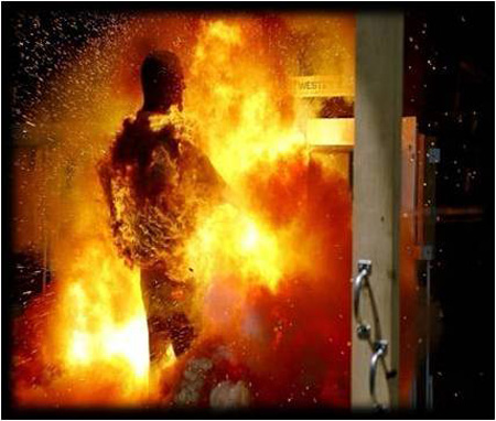
Arc flash is a high-energy electrical explosion caused by a fault through air. It produces extreme heat, pressure waves, and molten metal that can seriously injure unprotected workers. While arc flash and arc blast are distinct, an arc fault can originate from insulation breakdown or wiring damage and quickly intensify conditions.
Fire hazards arise when electrical faults, overloaded conductors, or damaged insulation ignite surrounding materials. Electrical fires often occur inside walls or equipment enclosures, making them difficult to detect early.
Explosion hazards exist where electrical equipment is installed in atmospheres containing flammable gases, vapours, or dust. Even low-energy sparks or static discharges can ignite these environments.
Secondary injuries include falls or impact injuries resulting from involuntary muscle reactions or arc-blast forces that throw workers from ladders or platforms.
Electricity Safety in Real Work Tasks
Electrical hazards are most commonly encountered during specific job activities. These include working on energized panels or switchgear, troubleshooting live circuits, performing maintenance on motors and drives, operating substations, and installing or modifying wiring systems. Confined spaces, damp environments, and industrial facilities increase risk due to limited movement, conductive surfaces, and higher fault currents. Understanding how hazards relate to actual job tasks is essential for effective risk assessment and control. Read our electrical safety tips page for advice on how to avoid hazards.
Preventing Electrical Injuries
Preventing electrical incidents requires practical controls rather than theoretical explanations. Key prevention measures include:
-
De-energizing circuits before work whenever possible and verifying the absence of voltage
-
Applying lockout and tagout procedures to prevent unexpected energization
-
Maintaining safe approach distances from exposed energized parts
-
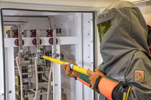
Using appropriate personal protective equipment such as arc-rated clothing, gloves, face shields, and insulated tools
-
Installing and maintaining grounding systems and ground-fault circuit interrupters to reduce shock risk
-
Keeping electrical equipment properly enclosed, maintained, and labeled
-
Providing task-specific electrical safety training for workers
These measures work together to reduce both the likelihood of an incident and the severity of injury if one occurs.
Regulatory Standards and Training Requirements
Recognized standards and regulations govern electrical safety in the workplace. In the United States, OSHA requires employers to protect workers from electrical hazards and references consensus standards for compliance. NFPA 70E provides detailed guidance on electrical safe work practices, arc-flash risk assessment, shock protection boundaries, and arc flash PPE selection. In Canada, CSA Z462 serves a similar role. These standards apply when employees are exposed to energized electrical equipment during installation, operation, maintenance, or troubleshooting. Training is mandatory because safe electrical work depends on informed decision-making, hazard recognition, and the correct use of protective measures.
Low-Voltage and High-Voltage Safety
Electrical safety is not limited to high-voltage systems. Voltages above 50 volts can cause serious injury, and even lower voltages can be lethal under adverse conditions, such as wet skin or confined contact points. High-voltage systems increase risk due to greater fault energy and arc-flash potential, but low-voltage systems remain a leading cause of electrical injuries because they are often underestimated. For context on regulatory and industry thresholds, see what is considered high voltage and how those limits are defined.


Arc Flash Versus Shock Hazards
Shock hazards involve current passing through the body, while arc-flash hazards involve thermal and blast effects from an electrical fault. A worker may be protected against shock yet still be exposed to severe arc flash injuries. Effective electrical safety programs address both hazards separately and apply appropriate controls for each.
Electricity Safety in Homes
In residential settings, electrical safety focuses on proper wiring, intact cords and plugs, grounding, and GFCI protection near water sources. Ground faults occur when current flows along an unintended path, and GFCIs are designed to interrupt that current quickly to prevent serious injury. Homeowners play a critical role by maintaining electrical systems, inspecting extension cords and avoiding unsafe modifications. Understanding the nature of a ground fault helps explain why GFCIs trip quickly to prevent shock.
Why Electricity Safety Matters
Electrical incidents are often sudden, severe, and preventable. Injuries can permanently affect workers, families, and organizations, while fires and explosions can shut down operations and destroy facilities. Electricity safety matters because it protects lives, ensures regulatory compliance, and supports reliable system operation. By understanding hazards, applying proven controls, and maintaining proper training, organizations and individuals can significantly reduce electrical risk and create safer environments wherever electrical energy is used. For clarity on terminology used across these standards, consult this electricity terms glossary for consistent definitions.
Related Articles

