What is Voltage?
By Harold WIlliams, Associate Editor
Voltage is the electrical potential difference that drives electric current through a circuit. Measured in volts, it represents energy per unit charge and determines how electrical systems deliver power safely and efficiently.
What is Voltage?
Voltage describes the electrical force that causes a charge to move within a circuit. It represents the difference in electrical potential energy between two points and determines how strongly electrons are pushed through a conductor. Without voltage, electrical charge remains stationary, and no current can exist.
Because voltage cannot be directly observed, it is often explained using analogies. One common analogy is water pressure in a pipe. Increased pressure moves more water, just as higher voltage moves electric charge more forcefully through a circuit. Another helpful comparison is gravitational potential energy. A ball at the top of a hill has stored energy that becomes motion when released. In the same way, voltage represents stored electrical energy that becomes current when a circuit is completed. A strong grasp of voltage begins with the fundamentals of electricity fundamentals, which explain how current, resistance, and power interact in circuits.
A third perspective is to view voltage as the action of a pump. A battery or generator supplies energy that continuously moves charge through a system. When that energy source is removed, charge flow stops. Together, these comparisons illustrate that voltage is the driving force that enables electrical systems to function. Since voltage and Current are inseparable, Ohm’s Law shows how resistance influences the flow of electricity in every system.
Voltage as Electrical Potential in Physics
In precise physical terms, voltage is defined as the amount of work required to move an electric charge between two points. This relationship is expressed mathematically as:
V = W / q
where V is voltage (in volts), W is the work or energy (in joules), and q is the charge (in coulombs). This equation shows that one volt equals one joule of energy per coulomb of charge.
Voltage is closely linked to current and resistance through Ohm’s Law:
V = I × R
In circuit analysis, voltage is also described through Ohm’s Law, which relates it to current and resistance:
V = I × R
where I is current (in amperes) and R is resistance (in ohms). This simple but powerful formula explains how voltage, current, and resistance interact in every electrical system.
Ohm’s Law and Measuring Voltage
This relationship shows that voltage increases as more current is required to overcome the resistance in a circuit. Engineers rely on this principle to design safe and efficient systems, from small electronic devices to industrial power networks.
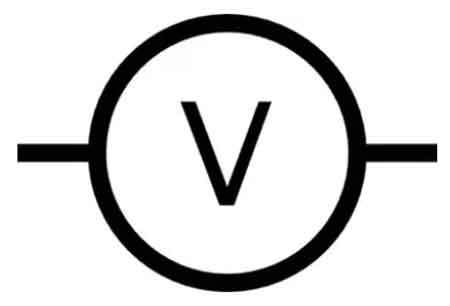
The unit of voltage, the volt, is named after Alessandro Volta, whose early work led to the invention of the first chemical battery. Today, voltage is measured using a voltmeter, which compares the electrical potential between two points in a circuit. The history of voltage is closely tied to the History of Electricity, where discoveries by pioneers like Volta and Franklin have shaped modern science.
Electric Fields and Charge Distribution
An electric potential difference between two points produces an electric field, represented by electric lines of flux (Fig. 1). There is always a relatively positive pole, with fewer electrons, and one that is relatively negative, with more electrons. The positive pole does not necessarily have a deficiency of electrons compared with neutral objects, and the negative pole might not have a surplus of electrons compared with neutral objects. What matters is the difference in charge between the two poles, which creates the force that moves electrons.
Fig 1. Electric lines of flux always exist near poles of electric charge.
Voltage Magnitude and Measurement Scales
The unit of voltage is V. Sometimes, smaller units are used. For example, the millivolt (mV) is equal to a thousandth (0.001) of a volt, and the microvolt (uV) is equal to a millionth (0.000001) of a volt. Larger voltage levels are also common. One kilovolt (kV) equals one thousand volts, while one megavolt (MV) equals one million volts. When comparing supply types, the distinction between Direct Current and AC vs DC shows why standardized voltage systems are essential worldwide.
Electromotive Force and Power Distribution
The concept of voltage is closely related to electromotive force (EMF), the energy that drives electrons to flow through a circuit. A chemical battery is a common example of a voltage source that generates EMF. The negatively charged electrons in the battery are driven toward the positive terminal, generating an electric current.
In power distribution, three-phase electricity and 3 Phase Power demonstrate how higher voltages improve efficiency and reliability.
Voltage Drop and Circuit Performance
Voltage is a fundamental concept in electrical and electronic systems because it influences how circuits and devices behave. Ohm’s Law describes the relationship between voltage, current, and resistance, stating that the voltage across a resistor equals the product of the current and the resistance.
The voltage dropped across components in a circuit is critical when designing or analyzing electrical systems. Voltage drop occurs when components such as resistors, capacitors, and inductors consume part of the available energy. Engineers often analyze Voltage Drop to evaluate circuit performance, alongside concepts like Electrical Resistance.
AC and DC Voltage Applications
Voltage levels are standardized in both household and industrial applications to ensure safe and efficient operation. Residential systems typically operate at 110-240 volts, depending on the region, while industrial systems may operate at several kilovolts to reduce transmission losses.


Another key distinction is between alternating current and direct current. AC alternates periodically and is widely used because it can be transformed easily for long-distance transmission. DC maintains a constant direction and is commonly used in batteries, electronics, and storage systems.
Voltage as a Foundational Electrical Concept
Voltage is the driving force behind the flow of charge carriers in electrical circuits. Understanding voltage is essential for analyzing circuits, designing systems, and ensuring safe operation. From Alessandro Volta's early work to modern electrical infrastructure, voltage remains a foundational concept in electrical science. Foundational principles such as Amperes Law and the Biot Savart Law complement voltage by describing how currents and magnetic fields interact.
Related Articles

