Watthour Meter Explained


Watthour explained

A watthour meter measures electrical energy consumption in kilowatt-hours (kWh) for residential, commercial, and industrial applications, ensuring accurate billing, energy management, and compliance with utility standards.


What is a Watthour Meter?

✅ Measures total electrical energy in kilowatt-hours (kWh) over time

✅ Supports accurate billing, energy monitoring, and demand analysis

✅ Used in residential, commercial, and industrial revenue metering


Advancements in Watthour Meter Technology and Energy Measurement

Watthour meter technology plays a crucial role in modern electrical engineering and maintenance by providing accurate measurement and monitoring of energy consumption. These devices are indispensable for managing energy efficiency, optimizing power distribution, and ensuring compliance with regulatory standards. For electrical professionals, understanding how they operate and are maintained is essential to minimize energy losses and enhance the reliability of electrical systems. With the growing demand for precise energy data in both residential and industrial applications, staying informed about advancements in watthour meter technology is more important than ever. Understanding how a watthour is calculated helps clarify how a watthour meter tracks total energy usage for accurate billing. 


How Induction Type Single Phase Watt Hour Meters Work

Induction type meters, commonly used as single phase watt hour meters, provide accurate measurement of electrical energy consumption in residential and small commercial installations.

Your electric utility is not too interested in how much power you're consuming for one ap­pliance or even how much power a single household is drawing at any given time. By far the greater concern is the total energy that is used over a day, a week, a month or a year. Electrical energy is measured in watt-hours or, more commonly for utility pur­poses, in kilowatt-hours (kWh). The device that measures this consumption is the watt-hour meter or kilowatt-hour meter. For a deeper understanding of the units used in metering, see our guide on electrical energy and how it is measured in kilowatt-hours.

The most common method for measuring electrical energy is by using a small elec­tric motor device, whose speed depends on the current, and thereby on the power at a constant voltage. The number of turns of the motor shaft, in a given length of time, is di­rectly proportional to the number of watt hours consumed. The motor is placed at the point where the utility wires enter the house, apartment or building. This is usually at a point where the voltage is 234 V. This is split into some circuits with 234 V, for heavy-duty appliances such as the oven, washer and dryer, and the general household circuits for lamps, clock radios and television sets. The principles behind watthour meters are closely tied to basic electricity and the relationship between active power and time.


Understanding the Spinning Disk in Electromechanical Watthour Meters

You've surely seen the little disk in the utility meter going around and around, sometimes fast, other times slowly. Its speed depends on the power you're using. The total number of turns of this little disk, every month, determines the size of the bill you will get, as a function also, of course, of the cost per kilowatt hour for electricity.

Kilo-watt-hour meters count the number of disk turns by means of geared, rotary drums or pointers. The drum-type meter gives a direct digital readout. The pointer type has several scales calibrated from 0 to 9 in circles, some going clockwise and others go­ing counterclockwise. Mechanical and electronic meters both rely on the concepts of electrical resistance and current to provide precise readings.


How to Read a Pointer-Type Watthour Meter Accurately

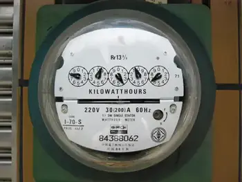
Reading a pointer-type utility meter is a little tricky because you must think in whatever direction (clockwise or counterclockwise) the scale goes. An example of a pointer-type utility meter is shown in Fig. 3-11. Read from left to right. For each little meter, take down the number that the pointer has most recently passed. Write down the rest as you go. The meter in the figure reads 3875 kWh. If you want to be really pre­cise, you can say it reads 3875-1/2 kWh. To place watt hour metering in historical context, explore our history of electricity page and learn how early meters evolved into today’s advanced devices.


Fig. 3-11 An example of a utility kilo-watthour meter. The reading is a little more than 3875 kWh.


Related Articles


Related News

Definition of a Rectifier

Definition of a rectifier explains AC to DC conversion using diodes, bridge or full-wave circuits, filters, and regulators to supply stable DC, reduce ripple, and power electronics, chargers, and DC motor drives.


What Is the Definition of a Rectifier?

An explanation of devices that convert AC to DC using diodes and filtering to deliver regulated, low-ripple DC power.

✅ Converts alternating current to direct current via diodes

✅ Topologies: half-wave, full-wave, bridge rectifier

✅ Uses filters and regulators to minimize ripple and stabilize DC


Understanding the definition of a rectifier is fundamental to grasping the complexities of power electronics and electrical engineering. Rectifiers are pivotal in converting AC power to DC power, a critical process for operating numerous electronic devices. By delving into the intricacies of half-wave, full-wave, and bridge rectifiers, as well as the silicon-controlled rectifier, it becomes clear that these devices are crucial in shaping the modern world of electronics. For readers new to the basics, an overview of the difference between AC and DC can clarify foundational concepts.


In electrical engineering, the definition encompasses a vital device that plays a crucial role in converting alternating current (AC) into direct current (DC). It  is an essential component in power electronics. It facilitates the conversion of AC power, commonly used in households and businesses, to DC power that electronic devices rely on. To contextualize this conversion, understanding alternating current behavior in typical distribution systems explains the need for rectification.

They come in various forms, such as diodes, mercury arc valves, and silicon-controlled rectifiers (SCRs). A diode, the most basic rectifying component, allows current to flow in only one direction. This feature helps convert AC power, which alternates direction, to DC power that flows in a single, continuous direction. For measurement and notation conventions, see how DC current is defined and applied in circuit analysis.

AC to DC conversion regulates voltage to create a steady and reliable energy supply. Throughout this conversion, rectifiers often assume different configurations depending on the specific application or requirement. Two popular configurations are the half-wave rectifier and the full-wave rectifier. Downstream stabilization is often handled by a voltage regulator that smooths residual ripple and safeguards loads.

A half-wave type allows only one half of the AC waveform to pass through while blocking the other half. This type is relatively simple and cost-effective but has a few downsides, such as lower efficiency and increased ripple voltage. Ripple voltage refers to the residual periodic variation of the DC output voltage. The result is an unsteady DC output, which might be undesirable in certain applications.

On the other hand, the full-wave type allows both halves of the AC waveform to pass through, effectively doubling the output frequency and reducing the ripple voltage. This configuration improves efficiency and provides a smoother, more consistent DC output voltage. The full-wave type has two primary forms: the center-tap configuration and the bridge rectifier.

The bridge rectifier is a highly efficient configuration that uses four diodes in a specific arrangement. This configuration eliminates the need for a center-tapped transformer, a key component in center-tap full-wave rectifiers, thus reducing overall size and cost. In addition, the bridge rectifier provides better voltage regulation and reduced harmonic distortion, making it ideal for various applications. For consistent terminology across datasheets, reviewing key electricity terms can prevent misinterpretation during design.

They serve numerous purposes in various fields. For instance, they are used in power supply circuits of electronic devices, battery chargers, and welding equipment. In addition, they help in voltage regulation for DC power supplies and extract radio signals from transmitted modulated signals. Many of these uses depend on stable direct current characteristics to ensure predictable device behavior.

Silicon-controlled rectifiers (SCRs) represent a more advanced type of rectifier. As silicon-based semiconductor switches, SCRs can control large amounts of current with a small input signal. This ability to manage current flow in a controlled manner sets SCRs apart from regular rectifiers, like diodes. As a result, SCRs are often used in power control applications, such as motor speed controllers, light dimmers, and temperature regulators.

Understanding how rectifiers play a pivotal role in industries and everyday applications is essential. One such application is in electric vehicles (EVs), where rectifiers contribute to charging systems by converting AC power from the grid to DC power for charging the battery. Additionally, they are utilized in renewable energy systems, like solar power and wind power, to convert the harvested energy into a stable and usable form for various applications. At a broader level, a concise electricity definition helps frame how conversion stages integrate with generation, storage, and loads.

Another application is in telecommunications equipment, where they help maintain a continuous and stable power supply. In the aviation and marine industries, rectifiers ensure sensitive equipment operates with minimal interference from fluctuating power sources. Moreover, they are employed in power supply units of medical devices, computers, and other critical equipment that demand stable power supplies.


How does it work in AC to DC conversion?

Its primary function is to convert AC voltage, which periodically reverses direction, into DC voltage, which flows in one direction. Its simplest form it consists of a diode, which allows current to pass in only one direction. When connected to an AC power source, the diode rectifies the current by blocking the negative half-cycles of the AC waveform. More advanced configurations, like full-wave rectifiers and bridge rectifiers, rectify both the positive and negative half-cycles, increasing efficiency and providing a smoother output.


What are the differences between half-wave and full-wave rectifiers?

The key difference between half-wave and full-wave rectifiers lies in their efficiency and output. A half-wave type only allows one-half of the AC waveform to pass through, blocking the other half. As a result, it has lower efficiency, increased ripple voltage, and produces an unsteady DC output.

On the other hand, a full-wave type allows both halves of the AC waveform to pass through, leading to increased efficiency and reduced ripple voltage. In addition, the full-wave type produces a smoother, more consistent DC output voltage, making it more suitable for applications that require a stable power supply. The full-wave type can be implemented using a center-tap or bridge rectifier configuration.


Related Articles

View more

Equivalent Resistance

Equivalent resistance is the total resistance of a circuit that simplifies multiple resistors into a single resistor. It is calculated differently for series and parallel circuits, helping determine current flow, voltage distribution, and overall power consumption in electrical networks.


What is Equivalent Resistance?

Equivalent resistance is a crucial concept for individuals working with electrical circuits. It: 

✅ Represents the single resistance that replaces multiple resistors in a circuit.

✅ Simplifies calculations of current, voltage, and power.

✅ Found using series or parallel formulas based on resistor arrangement.

By mastering the calculation methods for series and parallel circuits, understanding the relationship with Ohm's law, and applying Kirchhoff's laws in more complex situations, you can efficiently analyze and design electrical systems that meet the requirements of various applications. Furthermore, by incorporating equivalent resistance calculations into your skillset, you'll be better prepared to tackle the exciting challenges presented by the ever-evolving world of electronics and power systems.


Equivalent Resistance in Series vs. Parallel Circuits

Configuration Formula Key Characteristics Example Calculation
Series R_eq = R1 + R2 + R3... Same current flows through all resistors; total resistance increases; voltage drop varies across components. For R1=4Ω, R2=6Ω: R_eq = 4Ω + 6Ω = 10Ω
Parallel 1/R_eq = 1/R1 + 1/R2 + 1/R3... Same voltage across each resistor; total resistance decreases; current divides among paths. For R1=4Ω, R2=6Ω: 1/R_eq = 1/4 + 1/6 = 0.416 → R_eq ≈ 2.4Ω

To calculate the equivalent resistance of a network, it is often necessary to determine the sum of the individual resistances. This involves adding the resistance values of each individual resistor in the network, providing a baseline for further calculations. This is a resistance formula for a single resistor, as well as for calculating resistors connected in parallel or in series.

Electrical resistance (R) is a measure of the opposition to the flow of electric current within a circuit. It is determined by the material and dimensions of the conductor, as well as the temperature and other environmental factors. It is measured in ohms (Ω), with lower R indicating greater conductivity and vice versa.


Equivalent Resistance Formula

When a group of resistors is connected end-to-end, they form a series. In a series circuit, the total resistance is equal to the sum of the individual Rs, as current must flow through each resistor in turn. The equivalent resistance of a series circuit is calculated by adding the values of each individual resistor:

Req = R1 + R2 + R3 + ...

Resistors connected across the same potential difference, or applied voltage, are referred to as being connected in parallel. In a parallel circuit, the total R is less than the R of any individual resistor as the current divides among the resistors. The equivalent resistance of a parallel circuit is calculated using the reciprocal formula:

1/Req = 1/R1 + 1/R2 + 1/R3 + ...

Equivalent resistance is the single R value that can replace a group of resistors in a circuit, offering the same overall R. This simplifies circuit analysis and allows for more straightforward calculations of current and voltage values.

Ohm's law is an essential principle in electronics and relates closely to equivalent resistance. Ohm's law states that the current (I) flowing through a resistor is directly proportional to the applied voltage (V) and inversely proportional to the R. The equation is:

V = IR

By calculating equivalent resistance for a given circuit, we can use Ohm's law to determine the overall current flowing through the circuit and the voltage drops across each resistor.


Series and parallel circuits exhibit different properties when it comes to equivalent resistance. In series circuits, the overall R increases with the addition of more resistors, which means the total current will decrease. In parallel circuits, adding more resistors results in a decrease in total resistance, causing an increase in total current. Understanding these differences is crucial for designing circuits that meet specific electrical requirements.


Kirchhoff's Law

Kirchhoff's laws are another essential tool for calculating equivalent resistance in more complex circuits that cannot be simplified as purely series or parallel. Kirchhoff's current law (KCL) states that the sum of currents entering a junction in a circuit must equal the sum of currents leaving the junction. Kirchhoff's voltage law (KVL) asserts that the sum of the voltages around any closed loop in a circuit must equal zero. By applying these laws, we can create a system of equations to solve for unknown resistance values in a network, ultimately determining the equivalent resistance.


Real-World Applications

Real-world applications of equivalent resistance can be found in various fields, such as electronics, power distribution, and telecommunications. For example, various components have different R values in electronic devices, such as smartphones. Calculating the equivalent resistance enables engineers to design efficient power management systems, ensuring optimal performance and extended battery life. In power distribution networks, equivalent resistance calculations are essential for determining voltage drops and current values across transmission lines, enabling the design of efficient and reliable power delivery systems.

Understanding equivalent resistance is vital for professionals and students who deal with electrical circuits. From simplifying complex networks to designing efficient circuits, equivalent resistance plays a central role in analyzing and developing modern electronic systems. Familiarity with this concept and associated principles like Ohm's law and Kirchhoff's laws ensures a strong foundation for anyone working with electronics, power systems, and telecommunications.


Technology Advances

As technology advances, the importance of equivalent resistance in designing and analyzing new devices and systems will only grow. Calculating and understanding equivalent resistance enables engineers to push the boundaries of innovation and improve upon existing systems, resulting in more efficient, high-performance solutions for consumers and industries alike.

To further develop your understanding of equivalent resistance and related concepts, consider exploring the wealth of educational resources available online and in textbooks, as well as seeking hands-on experience through workshops or real-world projects. Applying this knowledge to practical scenarios will enable you to tackle various electrical and electronic challenges.

Related Articles


View more

Dynamic Electricity Explained

Dynamic electricity is the continuous flow of electric charge—electric current—through a conductor, typically driven by a voltage source. Think of it like water flowing in a pipe, where electrons move uniformly to carry energy.


What is Dynamic Electricity?

Dynamic electricity refers to the continuous movement of electric charges, commonly known as electric current.

  • Describes the flow of electrons or electric charge through a conductor

  • Facilitates energy transfer, enabling devices and machines to operate

  • Used in powering household appliances, industrial processes, lighting, and electronics

It is the continuous flow of electric charges through a conductor, commonly referred to as electric current. Think of it like water flowing through a pipe: voltage acts as water pressure, current as the flow of water, and resistance as the size of the pipe. This motion of electrons is what powers devices, lights homes, and drives entire industries.

Unlike static electricity, which involves charges at rest, dynamic electricity is defined by the constant movement of charge carriers, making it the foundation of modern electrical systems. To understand how voltage, current, and resistance interact in circuits, see our detailed guide on Ohm’s Law.

It depends on the movement of charges through conductive materials. Learn more about the difference between conductors and electrical insulators.

Dynamic electricity is closely tied to the concept of electrical energy, which is produced when an energy source creates movement between charges. A negative charge is naturally drawn toward a positively charged region, and objects with opposite charges will attract one another. This interaction between positive and negative charges is the foundation of current flow. Every type of electrical system, from simple batteries to complex power grids, relies on this basic principle to generate and transfer usable energy.


How It Works (Voltage, Current, Ohm’s Law)

Dynamic electricity occurs when a voltage difference is applied across a conductor, such as copper or aluminum wire. This creates an energy imbalance that causes electrons to flow from one end to the other.

  • Electrons drift slowly, but the electrical effect travels nearly at the speed of light, allowing instant energy transfer.

  • The flow of current is governed by Ohm’s Law: V = IR, where voltage (V) equals current (I) times resistance (R).

  • Moving charges generate magnetic fields and produce heat, demonstrating the role of resistance in circuits and enabling the operation of motors, electromagnets, and heating devices.

  • Current is measured in amperes (A), typically using an ammeter or other measurement instruments.

Electric current is measured in amperes, a unit explained in our introduction to electrical current.

The safe handling of flowing charges requires proper electrical grounding techniques to prevent hazards.

Analogy: Imagine marbles in a tube. Push one marble in, and the entire line shifts almost instantly. Similarly, electron movement is slow, but the effect propagates quickly through the entire circuit.


AC vs DC Explained

Type of Current Description Common Uses Advantages
Direct Current (DC) Electrons flow in a single, steady direction Batteries, electronics, solar panels, EVs Stable output, essential for digital devices and storage systems
Alternating Current (AC) Electron flow reverses direction periodically Power grids, appliances, and industrial systems Efficient long-distance transmission, adaptable to transformers


  • Why AC? Its ability to change voltage levels makes it ideal for transmitting energy over long distances with minimal energy loss.
  • Why DC? Critical for low-voltage devices, renewable integration, and battery storage, where stable current is required.

For a deeper look at how alternating current functions in grids, see our overview of alternating current.

Direct current plays a vital role in storage and electronics. Explore its applications on our page on direct current.


Everyday Applications

Dynamic electricity drives nearly every aspect of modern life:

  • Homes: power lighting, appliances, heating, and electronics.

  • Industry: runs motors, automation systems, and manufacturing equipment.

  • Transportation: essential for electric vehicles, rail systems, and aviation technologies.

  • Renewable energy: harnessed by solar panels, wind turbines, and hydroelectric systems, which is then transmitted via power grids over long distances through reliable power transmission systems.

  • Energy storage: stored in batteries to support grid reliability and electric mobility.

  • Communication systems: support telecom networks, internet infrastructure, and data centers.

In renewable energy systems, dynamic electricity is produced and stored for later use. Learn how it relates to energy storage.

The flow of current must be managed carefully in fault conditions. For details, see our guide on fault current calculation.


Safety and Control

Because moving charges create heat, sparks, and electromagnetic fields, electrical circuits are designed with protective devices:

  • Circuit breakers and fuses prevent overheating and fire risks.

  • Insulation and grounding ensure safe handling of conductors.

  • Control systems regulate current flow for efficiency and reliability.

Circuit safety relies on protective systems. Explore our page on electrical protection for more details.


Static vs Dynamic Electricity

Understanding the difference is key:

  • Static

    • Charges accumulate on surfaces.

    • It can cause small shocks or sparks.

    • Temporary and uncontrolled.

  • Dynamic

    • Charges move continuously through conductors.

    • Power devices and grids.

    • Reliable and controllable.


Future Challenges and Developments

The demand for dynamic electricity is expanding as society transitions to net-zero energy systems. Key developments include:

  • Smart grids to balance supply and demand.

  • Advanced energy storage to integrate renewable sources.

  • Global electrification in emerging economies, driving higher usage worldwide.

It will continue to shape technology, transportation, and sustainability goals in the decades ahead.


Frequently Asked Questions


What is the difference between static and dynamic electricity?

Static involves charges at rest, while dynamic is defined by moving charges, producing electric current used to power systems.


Why is it important in daily life?

It powers homes, industries, transport, communication, and renewable energy systems, making it the foundation of modern civilization.


How is it measured?

It is measured in amperes (A), using tools like ammeters to detect the flow of current in a circuit.


Related Articles


View more

Electricity Generator

Electricity generator converts mechanical energy to electrical power via electromagnetic induction using a prime mover, alternator, stator, and rotor, delivering regulated AC/DC output, high efficiency, and stable voltage and frequency.


What Is an Electricity Generator?

An electricity generator converts mechanical energy to electric power using electromagnetic induction, AC or DC.

✅ Converts rotational torque into regulated AC or DC output

✅ Uses stator, rotor, and excitation for voltage regulation

✅ Applied in power plants, gensets, microgrids, and renewables


An Electricity Generator can create electricity by converting mechanical energy into electrical current that can be used in electrical systems. Wind turbines house such generators to convert the kinetic energy of wind into power that can feed power grids. involve the production of electrons that are a part of every atom,. Electricity is what results when electrons are flowing through a conductor. Ultimately, all that is needed to generate electricity is a metal wire for a conductor and a catalyst to start the electrically charged electrons flowing. You see, unlike natural gas and other fossil fuels that are mined from the Earth, electricity is a manufactured product. Most generators operated by electric utilties are alternating current (ac) generators but there are still some direct current (dc) generators in existence. For a clear primer on charge, current, and how generators relate to these basics, see what is electricity to ground these concepts.

Alternating current is easily generated by means of a rotating magnet windings in a coil of wire, or by a rotating coil of wire inside a powerful magnet. In either case, the ac appears between the ends of the length of wire. This takes place in an electricity generator, which was invented by Michael Faraday. A portable generator can be used as backup power during a power outage. If you want a step-by-step view of induction and circuit behavior, consult how electricity works for context beyond this overview.

The ac voltage that a generator (motor) can develop depends on the strength of the magnets field, the number of turns in the wire coil, and the speed at which the magnet or coil rotates. The ac frequency depends only on the speed of rotation. Normally, for utility ac, this speed is 3,600 revolutions per minute (rpm), or 60 complete revolutions per second (rps), so that the frequency is 60 Hz. Design choices that set coil turns, flux, and rotational speed are discussed in how electricity is generated with practical examples.

When a load, such as a light bulb or heater, is connected to an ac generator, it becomes more difficult to turn the generator. The more power needed from a generator, the greater the amount of power required to drive it. This is why it is not possible to connect a generator to, for instance, your stationary bicycle, and pedal an entire city into electrification. There's no way to get something for nothing. The electrical power that comes out of a generator can never be more than the mechanical power driving it. In fact, there is always some energy lost, mainly as heat in the generator. Your legs might generate 50 W of power to run a small radio, but nowhere near enough to provide electricity for a household. Realistic scenarios for human power and small prime movers are outlined in generate electricity to help size expectations.

The efficiency of a generator is the ratio of the magnet generate power output to the driving power, both measured in the same units (such as watts or kilowatts), multiplied by 100 to get a percentage. No generator is 100 percent efficient. But a good one can come fairly close to this ideal. Typical loss mechanisms and efficiency ranges across technologies are compared in electricity generation for further reading.

At power plants, the power generators can be huge. Each one can be as big as a house. In a power plant, each electricity generator is driven by a massive turbine. Often, steam drives the turbine, and the steam is obtained via heat derived from natural energy source, like falling water. Capacity factors, fuel choices, and turbine types are covered in electricity production to illustrate real-world plant operation.

There are many different sources of electricity and many different ways electricity can be produced and consumed. For instance, modern wind turbines are explained in electricity windmill with details on siting, capacity, and grid integration.


Related Articles

View more

Understanding Current

Current is the flow of electric charge in circuits, defined by amperage, driven by voltage, limited by resistance, described by Ohm’s law, and fundamental to AC/DC power systems, loads, conductors, and electronic components.


What Is Current?

Current is charge flow in a circuit, measured in amperes and governed by voltage and resistance.

✅ Measured in amperes; sensed with ammeters and shunts

✅ Defined by Ohm’s law: I = V/R in linear resistive circuits

✅ AC alternates; DC is steady; sets power transfer P = V*I


Current is best described as a flow of charge or that the charge is moving. Electrons in motion make up an electric current. This electric current is usually referred to as “current” or “current flow,” no matter how many electrons are moving. Current is a measurement of a rate at which a charge flows through some region of space or a conductor. The moving charges are the free electrons found in conductors, such as copper, silver, aluminum, and gold. The term “free electron” describes a condition in some atoms where the outer electrons are loosely bound to their parent atom. These loosely bound electrons can be easily motivated to move in a given direction when an external source, such as a battery, is applied to the circuit. These electrons are attracted to the positive terminal of the battery, while the negative terminal is the source of the electrons. The greater amount of charge moving through the conductor in a given amount of time translates into a current. For a concise overview of how moving charges create practical circuits, see this guide to current electricity for additional context.


The System International unit for current is the Ampere (A), where


That is, 1 ampere (A) of current is equivalent to 1 coulomb (C) of charge passing through a conductor in 1 second(s). One coulomb of charge equals 6.28 billion billion electrons. The symbol used to indicate current in formulas or on schematics is the capital letter “I.” To explore the formal definition, standards, and measurement practices, consult this explanation of the ampere for deeper detail.

When current flow is one direction, it is called direct current (DC). Later in the text, we will discuss the form of current that periodically oscillates back and forth within the circuit. The present discussion will only be concerned with the use of direct current. If you are working with batteries or electronic devices, you will encounter direct current (DC) in most basic circuits.

The velocity of the charge is actually an average velocity and is called drift velocity. To understand the idea of drift velocity, think of a conductor in which the charge carriers are free electrons. These electrons are always in a state of random motion similar to that of gas molecules. When a voltage is applied across the conductor, an electromotive force creates an electric field within the conductor and a current is established. The electrons do not move in a straight direction but undergo repeated collisions with other nearby atoms. These collisions usually knock other free electrons from their atoms, and these electrons move on toward the positive end of the conductor with an average velocity called the drift velocity, which is relatively a slow speed. To understand the nearly instantaneous speed of the effect of the current, it is helpful to visualize a long tube filled with steel balls as shown in Figure 10-37. It can be seen that a ball introduced in one end of the tube, which represents the conductor, will immediately cause a ball to be emitted at the opposite end of the tube. Thus, electric current can be viewed as instantaneous, even though it is the result of a relatively slow drift of electrons. For foundational concepts that connect drift velocity with circuit behavior, review this basic electricity primer to reinforce the fundamentals.

Current is also a physical quantity that can be measured and expressed numerically in amperes. Electric current can be compared to the flow of water in a pipe. It is measureda at the rate in which a charge flows past a certain point on a circuit. Current in a circuit can be measured if the quantity of charge "Q" passing through a cross section of a wire in a time "t" (time) can be measured. The current is simply the ratio of the quantity of charge and time. Understanding current and charge flow also clarifies how circuits deliver electrical energy to perform useful work.


Electrical current is essentially an electric charge in motion. It can take either the form of a sudden discharge of static electricity, such as a lightning bolt or a spark between your finger and a ground light switch plate. More commonly, though, when we speak of current, we mean the more controlled form of electricity from generators, batteries, solar cells or fuel cells.  A helpful overview of static, current, and related phenomena is available in this summary of electricity types for quick reference.

We can think of the flow of electrons in a wire as the flow of water in a pipe, except in this case, the pipe of water is always full. If the valve on the pipe is opened at one end to let water into the pipe, one doesn't have to wait for that water to make its way all the way to the other end of the pipe. We get water out the other end almost instantaneously because the incoming water pushes the water that's already in the pipe toward the end. This is what happens in the case of electrical current in a wire. The conduction electrons are already present in the wire; we just need to start pushing electrons in one end, and they start flowing at the other end instantly. In household power systems, that push on conduction electrons alternates in direction as alternating current (AC) drives the flow with a time-varying voltage.


Current Formula

Current is rate of flow of negatively-charged particles, called electrons, through a predetermined cross-sectional area in a conductor.

 Essentially, flow of electrons in an electric circuit leads to the establishment of current.

q = relatively charged electrons (C)

t = Time

Amp = C/sec

Often measured in milliamps, mA


Related Articles

View more

Electrical Resistance Definition Explained

Electrical resistance definition explains how materials oppose current flow in circuits, measured in ohms, linked to voltage, resistivity, conductor geometry, temperature, and impedance, governed by Ohm's law and SI units in electronics.


What Is Electrical Resistance Definition?

It is the measure of how a material opposes electric current, equal to voltage divided by current and measured in ohms.

✅ Measured in ohms; per Ohm's law, resistance R equals voltage V over current I.

✅ Depends on material resistivity, length, cross-sectional area, and temperature.

✅ Key in circuit analysis, power dissipation, signal integrity, and safety.


Electrical Resistance Definition: ER occurs in an electrical circuit when current-carrying charged particles collide with fixed particles that make up the structure of the conductors. Resistance is measured in ohm. Resistance is the ohm w. Resistance occurs in every part of a circuit, including wires and especially power transmission lines. For a concise overview, see this introduction to electrical resistance to reinforce key definitions.

Dissipation of electric energy in the form of heat affects the amount of driving voltage required to produce a given current through the circuit. In fact, volts are mesured across a circuit divided by the current I (amperes) through that circuit defines quantitatively the amount of electrical resistance R. The ohm is the common unit of electrical resistance, equivalent to one volt per ampere and represented by the capital Greek letter omega, Ω. The electrical resistance of a wire is directly proportional to its length and inversely proportional to its cross-sectional area. Resistance also depends on the material of the conductor. For instance, the resistance of a conductor generally increases with increasing temperature the resistivity. This is why some conductors have almost zero resistance when cooled to extremely low temperatures, as is the case with superconductors, because of the relative resistivity of metals. There is a temperature coefficient of resistivity. If you need a refresher on potential difference and its role in circuits, review this explanation of voltage to connect the concepts.

Alternating-current resistors for current measurement require further design consideration. For example, if the resistor is to be used for current-transformer calibration, its ac resistance must be identical with its dc resistance within 1/100th% or better, and the applied voltage difference between its voltage terminals must be in phase with the current through it within a few tenths of a minute. Thin strips or tubes of resistance material are used to limit eddy currents and minimize "skin" effect, the current circuit must be arranged to have small self-inductance, and the leads from the voltage taps to the potential terminals should be arranged so that, as nearly as possible, the mutual inductance between the voltage and current circuits opposes and cancels the effect of the self-inductance of the current circuit. In (a) a metal strip has been folded into a very narrow U; in (b) the current circuit consists of coaxial tubes soldered together at one end to terminal blocks at the other end; in (c) a straight tube is used as the current circuit, and the potential leads are snugly fitting coaxial tubes soldered to the resistor tube at the desired separation and terminating at the center. These design choices are also easier to contextualize by comparing common types of resistors used for precise AC measurements.

Electrical Resistance coils consist of insulated resistance copper wire wound on a bobbin or winding form, hard-soldered at the ends to copper terminal wires. Metal tubes are widely used as winding form for dc resistors because they dissipate heat more readily than insulating bobbins, but if the resistor is to be used in ac measurements, a ceramic winding form is greatly to be preferred because it contributes less to the phase-defect angle of the resistor. The resistance wire ordinarily is folded into a narrow loop and wound bifilar onto the form to minimize inductance. This construction results in considerable associated capacitance of high-resistance coils, for which the wire is quite long, and an alternative construction is to wind the coil inductively on a thin mica or plastic card. The capacitive effect is greatly reduced, and the inductance is still quite small if the card is thin. When specifying coil assemblies, it helps to recall the standardized unit of electrical resistance so ratings and tolerances are interpreted consistently.

Resistors in which the wire forms the warp of a woven ribbon have lower time constants than either the simple bifilar- or card-wound types. Manganin is the resistance material most generally employed, but Evanohm and similar alloys are beginning to be extensively used for very high resistance coils. Enamel or silk is used to insulate the wire, and the finished coil is ordinarily coated with shellac or varnish to protect the wire from the atmosphere. Such coatings do not completely exclude moisture, and dimensional changes of insulation with humidity will result in small resistance changes, particularly in high resistances where fine wire is used. Material behavior, moisture effects, and long term stability are discussed further in this broader overview of electrical resistance for additional context.

Electrical Resistance boxes usually have two to four decades of resistance so that with reasonable precision they cover a considerable range of resistance, adjustable in small steps. For convenience of connection, terminals of the individual resistors are brought to copper blocks or studs, which are connected into the circuit by means of plugs or of dial switches using rotary laminated brushes; clean, well-fitted plugs probably have lower resistance than dial switches but are much less convenient to use. The residual inductance of decade groups of coils due to switch wiring, and the capacitance of connected but inactive coils, will probably exceed the residuals of the coils themselves, and it is to be expected that the time constant of an assembly of coils in a decade box will be considerably greater than that of the individual coils. Understanding how series and parallel combinations set the equivalent resistance will inform how decade boxes are deployed in complex networks.

Measurement of resistance is accomplished by a variety of methods, depending on the magnitude of the resistor and the accuracy required. Over the range from a few ohms to a megohm or more, an ohmmeter may be used for an accuracy of a few percent. A simple ohmmeter may consist of a milliammeter, dry cell, and resistor in a series circuit, the instrument scale being marked in resistance units, if you obey ohm law. For a better value, the voltage drop is measured across the resistor for a measured or known current through it. Here, accuracy is limited by the instrument scales unless a potentiometer is used for the current and voltage measurements. The approach is also taken in the wide variety of digital multimeters now in common use. Their manufacturers' specifications indicate a range of accuracies from a few percent to 10 ppm (0.001%) or better from the simplest to the most precise meters. Bridge methods can have the highest accuracy, both because they are null methods in which two or more ratios can be brought to equality and because the measurements can be made by comparison with accurately known standards. For two-terminal resistors, a Wheatstone bridge can be used; for four-terminal measurements, a Kelvin bridge or a current comparator bridge can be used. Bridges for either two- or four-terminal measurements also may be based on resistive dividers. Because of their extremely high input impedance, digital voltmeters that be used with standard resistors in unbalanced bridge circuits of high accuracy. For quick reference during test planning, the fundamental resistance formula clarifies how R, V, and I are related under Ohm law.

Digital multi meters are frequently used to make low-power measurements of resistors in the range between a few ohms and a hundred megohms or so. Resolution of such instruments varies from 1% of full scale to a part per million of full scale. These meters generally use a constant-current source with a known current controlled by comparing the voltage drop on an internal "standard" resistor to the EMF produced by a Zener diode. The current is set at such a level as to make the meter direct-reading in terms of the displayed voltage; that is, the number displayed by the meter reflects the voltage drop across the resistor, but the decimal point is moved and the scale descriptor is displayed as appropriate. Multimeters typically use three or more fixed currents and several voltage ranges to produce seven or more decade ranges with the full-scale reading from 1.4 to 3.9 times the range. For example, on the 1000-0 range, full scale may be 3,999.999 Q. Power dissipated in the measured resistor generally does not exceed 30 mW and reaches that level only in the lowest ranges where resistors are usually designed to handle many times that power. The most accurate multimeters have a resolution of 1 to 10 ppm of range on all ranges above the 10-0 range. Their sensitivity, linearity, and short-term stability make it possible to compare nominally equal resistors by substitution with an uncertainty 2 to 3 times the least count of the meter. This permits their use in making very accurate measurements, up to 10 ppm, or resistors whose values are close to those of standards at hand. Many less expensive multimeters have only two leads or terminals to use to make measurements. In those cases, the leads from the meter to the resistor to be measured become part of the measured


Related Articles

View more

Sign Up for Electricity Forum’s Newsletter

Stay informed with our FREE Newsletter — get the latest news, breakthrough technologies, and expert insights, delivered straight to your inbox.

Electricity Today T&D Magazine Subscribe for FREE

Stay informed with the latest T&D policies and technologies.
  • Timely insights from industry experts
  • Practical solutions T&D engineers
  • Free access to every issue

Download the 2025 Electrical Training Catalog

Explore 50+ live, expert-led electrical training courses –

  • Interactive
  • Flexible
  • CEU-cerified