What is Impedance? Explained
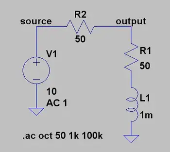
Impedance is the total opposition a cable or circuit offers to alternating current (AC). It combines resistance and reactance, measured in ohms (Ω), and determines how easily AC signals move through a circuit, affecting voltage, current, and power.
What is Impedance?
Impedance refers to the opposition that an electrical circuit presents to the flow of alternating current. It is a complex quantity that combines resistance and reactance, shaping how signals behave in AC systems.
✅ Combines resistance and reactance in AC circuits
✅ Measured in ohms and affects signal flow and power
✅ Essential in analyzing voltage, current, and circuit behavior
Understanding impedance (Z) is essential for anyone working with AC circuits. It influences how electrical energy flows, how efficiently components interact, and how systems handle varying frequencies. To understand how impedance interacts with voltage, explore our explanation of what is voltage and how it affects current flow in electrical circuits.
Electrical resistance is the opposition to direct current, while reactance opposes alternating current. Reactance arises from capacitors and inductors: capacitive reactance decreases with frequency, while inductive reactance increases. Together, these elements define the circuit’s impedance and its effect on current, voltage, and power transfer.
Impedance is crucial in AC circuit analysis because it enables engineers and technicians to calculate how voltage and current behave. This understanding facilitates efficient design, troubleshooting, and energy transfer, particularly when impedance matching is necessary for optimal performance. In AC systems, the behavior of inductors is described by inductance, which directly contributes to the reactive part of impedance.
Impedance Formula and Complex Representation
Impedance is defined mathematically by the formula:
Z = V / I
Where:
-
Z is impedance in ohms (Ω)
-
V is voltage (volts)
-
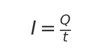
I is current (amperes)
This relationship is a natural extension of Ohm’s Law, which defines the link between voltage, current, and resistance in DC circuits. In AC analysis, impedance expands this concept by including reactance and phase angle.
In AC systems, impedance is expressed as a complex impedance:
Z = R + jX
Where:
-
R is resistance (real part)
-
X is reactance (imaginary part)
-
j is the imaginary unit
This representation accounts for both magnitude and phase angle, enabling the modelling of the interaction between voltage and current in AC circuits. Capacitors also play a key role, and understanding capacitance is essential to see how impedance decreases at higher frequencies.
Frequency, Phase Angle, and Reactance
Impedance depends on frequency. As frequency increases, reactance (especially inductive and capacitive) also changes, which shifts the phase angle between voltage and current.
-
Inductive reactance (XL = 2πfL) increases with frequency
-
Capacitive reactance (XC = 1 / 2πfC) decreases with frequency
As a result, the total impedance can change significantly depending on the signal. Engineers must consider this when analyzing harmonics or designing high-frequency systems. Learn how resistance contributes to impedance by reviewing what is electrical resistance and how it differs from reactance in AC systems.
Common Applications of Impedance
Understanding impedance is critical in many areas of electrical and electronic engineering:
-
Audio Systems: Proper impedance matching ensures maximum power transfer and sound clarity between amplifiers and speakers.
-
Radio Frequency (RF): Antenna design and transmission lines rely on precise impedance matching to minimize signal loss.
-
RLC Circuits: Impedance analysis enables tuning and resonance calculations in resistor-inductor-capacitor (RLC) networks.
-
Power Systems: Impedance affects fault current calculations, load flow, and harmonic analysis.
-
Phasor Analysis: Engineers use phasors to represent voltage and current in the frequency domain, relying on impedance to model AC behavior. For insights into the capacitive elements of impedance, see what is a capacitor and how it stores energy in electric fields.
Power System Impedance (Advanced)
At fundamental frequency, power systems are mostly inductive, and the equivalent impedance is often described as short-circuit reactance. While capacitive effects are typically minor in utility and industrial systems, they become significant in harmonic analysis. Short-circuit impedance, often derived from system studies, is a critical factor in these calculations.
Short-Circuit Reactance
If phase data is unavailable, engineers usually assume impedance is purely reactive—a reasonable approximation in many cases. However, transformer and line resistance may need to be considered for accurate harmonic modeling. The inductive reactance portion of impedance scales linearly with frequency, and engineers must carefully apply this when analyzing short-circuit conditions.
Transformer Resistance Effects
Resistance in transformers and conductors can change with frequency due to skin effect or eddy current losses. Large substation transformers, for example, may exhibit resistance that increases almost in proportion to frequency, which can help dampen resonance. In smaller transformers, winding resistance dominates and remains nearly constant until higher frequencies are reached. At utilization voltages, such as in industrial power systems, the service transformer’s impedance often accounts for more than 90% of total system impedance.
Transformer impedance in ohms can be estimated from the nameplate percentage impedance:
Z (Ω) = (Z% / 100) × (V² / kVA)
For instance, a 1,500 kVA transformer with a 6% impedance at 480 V has an equivalent impedance of approximately 9.22 Ω. This simplification is often sufficient to evaluate harmonic resonance risks and system behavior. For more on efficiency, review what the power factor is and its impact on AC systems.
Harmonic Considerations
One common mistake in harmonic analysis is neglecting to adjust reactance for frequency. The reactance at the h-th harmonic is determined from the fundamental reactance X1 by:
where h is the harmonic number and X1 is the fundamental reactance magnitude. (For capacitive branches specifically: XC,h = XC,1 / h, while inductive branches scale as XL,h = h × XL,1.)
In many power systems, resistance remains nearly unchanged up to the ninth harmonic. However, at higher frequencies, skin effect increases conductor resistance, and transformer eddy current losses further influence apparent resistance. These factors affect resonance conditions and can alter predictions of harmonic distortion.
Neglecting resistance generally yields a conservative, higher prediction of distortion. But when transformer effects dominate system behavior, resistance should be modeled more carefully. Impedance matching is especially important in such cases for ensuring stability and avoiding resonance issues in AC power systems. The impact of impedance extends to system-level issues like harmonic distortion, which can affect stability and power quality if not managed correctly.
Calculating Total Impedance
The total impedance (Z_total) of a circuit depends on how elements are connected:
Series circuits:
Z_total = √ (R_total² + (X_L – X_C)²)
Parallel circuits:
Z_total = 1 / (1/Z₁ + 1/Z₂ + …)
These calculations follow the same principles as Ohm’s Law, but are adapted for AC circuits where both resistance and reactance determine the current flow. By combining these components, engineers can predict circuit response, design filters, and ensure efficient energy transfer. Calculating impedance is a crucial part of power system analysis, where accurate models enable the prediction of current flow, voltage stability, and fault levels.
Impedance Matching and Spectroscopy
Impedance matching adjusts the source and load to the same impedance, maximizing power transfer and minimizing reflections. It is essential in audio systems, RF communications, and transmission line design.
Impedance spectroscopy extends the concept further, analyzing a material or device across a range of frequencies. This method reveals electrical properties such as conductivity, dielectric response, and electrochemical behavior, guiding the design of advanced materials and devices.
Conclusion
Impedance is a cornerstone of AC circuit analysis, uniting resistance and reactance into a single complex value that varies with frequency. From audio clarity to power system stability, impedance shapes how electricity flows and interacts in real-world systems. By mastering impedance—whether matching speaker loads, modeling harmonic resonance, or studying material properties—engineers and technicians can design more efficient, reliable, and safe electrical systems.
Related Articles


