Arc Flash Boundary Explained
By R.W. Hurst, Editor
CSA Z462 Arc Flash Training - Electrical Safety Essentials
Our customized live online or in‑person group training can be delivered to your staff at your location.

- Live Online
- 6 hours Instructor-led
- Group Training Available
Download Our OSHA 4474 Fact Sheet – Establishing Boundaries Around Arc Flash Hazards
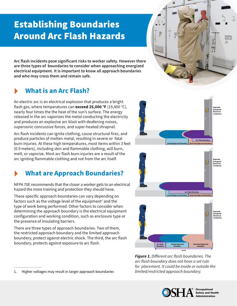
- Understand the difference between arc flash and electric shock boundaries
- Learn who may cross each boundary and under what conditions
- Apply voltage-based rules for safer approach distances
An arc flash boundary is the minimum safe distance from energized electrical equipment where a worker could suffer a second-degree burn from an arc flash event. It is calculated based on where incident energy reaches 1.2 calories per square centimeter (cal/cm²) according to NFPA 70E and CSA Z462 standards.
Request a Free Training Quotation
What is an Arc Flash Boundary?
In simple terms, the Arc Flash Boundary can be summarized as follows:
✅ The minimum safe distance from energized equipment where a worker could suffer a second-degree burn from an arc flash.
✅ Based on an incident energy level of 1.2 calories per square centimeter (cal/cm²) under NFPA 70E and CSA Z462 standards.
✅ Determined by factors such as system voltage, available fault current, clearing time, and equipment design.
The arc flash boundary (AFB) is the minimum safe distance from energized electrical equipment where a worker could suffer a second-degree burn from an arc flash event. It is calculated based on where the incident energy reaches 1.2 calories per square centimetre (cal/cm²). Defined by NFPA 70E and guided by IEEE 1584, the arc flash boundary determines required personal protective equipment (PPE), informs safe work practices, and restricts personnel entry into hazardous zones during energized tasks such as maintenance, testing, or troubleshooting.
For more details on calculated distances, see our arc flash boundary chart.
Purpose and Benefits of Establishing the AFB
This protection zone serves multiple safety functions:
-
Identifies zones of elevated thermal risk
-
Helps determine required PPE levels
-
Defines access control perimeters for qualified and unqualified personnel
-
Promotes planning for safe electrical work procedures
Visual indicators such as floor tape and posted signage help communicate the zone clearly to all workers, reinforcing situational awareness on the job site.
Test Your Knowledge About Arc Flash!
Think you know Arc Flash? Take our quick, interactive quiz and test your knowledge in minutes.
- Instantly see your results and score
- Identify strengths and areas for improvement
- Challenge yourself on real-world electrical topics
Who Determines the Arc Flash Boundary?
Qualified engineers or safety professionals conduct arc flash studies using data on system voltage, available fault current, protective device clearing times, and equipment configuration. These studies follow standardized calculation methods found in IEEE 1584, with applications enforced through NFPA 70E guidelines. While OSHA does not directly define arc flash parameters, it mandates the use of recognized industry standards, such as NFPA 70E, to maintain a safe working environment.
When working on or near any piece of equipment that remains energized, there is a serious risk of an arc flash occurring. This risk highlights the importance of restricting access to only qualified workers who have been trained in proper procedures and are equipped with the appropriate personal protective equipment (PPE). Without these precautions, anyone crossing the AFB could receive second-degree burns, which is why this zone exists—to define the minimum safe distance from the hazard.
How Is the AFB Calculated?
The boundary distance varies depending on several key factors:
-
System voltage
-
Available fault current
-
Duration of arc exposure (based on breaker/fuse clearing time)
-
Configuration of the equipment (open air vs. enclosed)
An example: for a 480V motor control center (MCC), the required safe distance may be 36 inches at an incident energy of 8 cal/cm². See: what is the arc flash boundary for 8 cal/cm².
Calculations can be performed manually using formulas from IEEE 1584 or with specialized arc flash analysis software. To see common calculated distances, refer to our arc flash boundary table by incident energy.
Approach Boundaries: Complementary Protection Zones
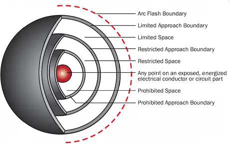
In addition to the AFB, NFPA 70E defines three approach boundaries for shock protection:
-
Limited Approach Boundary: The distance from exposed, energized parts where unqualified persons must be accompanied.
-
Restricted Approach Boundary: Area requiring additional PPE and safety documentation. Only qualified personnel can enter.
-
Prohibited Approach Boundary (no longer used in recent editions): Previously defined areas requiring same protection as direct contact.
To better understand these zones, visit our articles on the limited approach boundary, restricted approach boundary, and prohibited approach boundary.
These boundaries work in tandem with the AFB to ensure a layered approach to electrical safety.
Marking the AFB in the Workplace
To ensure arc flash boundaries are respected and understood, workplaces must make them clearly visible. Best practices include:
-
Applying floor marking tape to show calculated distances
-
Posting warning signs near electrical panels or switchgear
-
Labeling equipment with arc flash labels that include the distance and required PPE
-
Using temporary barriers or barricades during energized work
-
Training all staff to recognize these visual indicators and understand their meaning
Effective zone marking helps prevent accidental entry into high-risk zones and reinforces safe behavior throughout the facility.
Real-World Applications and Protective Value
In practical terms, this critical hazard zone is more than a theoretical line — it shapes real jobsite behavior. For example, a 480V panel with 8 cal/cm² of incident energy might require a boundary of 36 inches. Workers crossing this line must wear appropriate PPE, including an arc-rated suit, face shield, gloves, and hearing protection.
Arc flash boundaries also help define safe zones for unqualified personnel, guide pre-job briefings, and support lockout/tagout planning. By enforcing these boundaries, employers minimize the risk of injury and build a safety culture grounded in prevention and preparedness.
To minimize the risk of an arc flash incident, facilities must calculate the incident energy present at various points within the system and apply the appropriate NFPA 70E threshold limits. These boundaries are not arbitrary—they serve as part of a layered electrical safety perimeter that includes clearly marked approach boundaries for shock protection. Only qualified electrical workers, trained in hazard recognition and PPE requirements, are permitted to enter these zones when energized work is necessary, thereby reinforcing a structured and compliant safety protocol.
Sign Up for Electricity Forum’s Arc Flash Newsletter
Stay informed with our FREE Arc Flash Newsletter — get the latest news, breakthrough technologies, and expert insights, delivered straight to your inbox.
Enforcing Calculated Limits
Establishing and enforcing these calculated limits is not just a matter of compliance—it’s a matter of safety culture. The zone reflects a facility's commitment to preventing life-altering injuries and maintaining high standards for electrical work. It also supports the development of consistent arc flash training, pre-job briefings, and hazard awareness.
This minimum safe distance plays a crucial role in protecting workers from the thermal hazards associated with arc flash incidents. It defines the danger zone, informs PPE selection, and guides safe work practices. Organizations create safer work environments and meet their legal obligations by adhering to NFPA 70E, implementing zone signage, and conducting proper arc flash studies.
Frequently Asked Questions
What are the 3 boundaries for arc flash?
The three boundaries include the Limited Approach Boundary, the Restricted Approach Boundary (both related to electric shock protection), and the Arc Flash Boundary. Each boundary sets specific requirements under NFPA 70E, including the type of PPE required and the qualifications workers must possess to enter each zone safely.
What is the minimum arc flash boundary?
The arc flash boundary is the minimum distance from an energized conductor or circuit where the incident energy equals 1.2 cal/cm² (5.02 J/cm²). At this distance, a worker without proper PPE could suffer second-degree burns from an arc flash.
What is the boundary of arc flash 480v?
The arc flash boundary for 480V equipment is the distance from the potential arc source at which the incident energy reaches 1.2 cal/cm², sufficient to cause second-degree burns. This distance depends on factors such as fault current, system configuration, and the clearing time of protective devices.
How to calculate the arc flash boundary?
The arc flash boundary is calculated by determining the distance from an exposed energized conductor at which the incident energy reaches 1.2 cal/cm² (5.02 J/cm²), as specified in NFPA 70E. This marks the point where a worker without proper PPE could suffer second-degree burns.
Compliance Note
Note: The Prohibited Approach Boundary was removed in recent NFPA 70E revisions; however, it still appears in some legacy documentation and training materials. Facilities should align current practices with the latest edition of the standard.
Related Articles:


