Arc Flash Boundary Calculation: How to Determine Safe Working Distances

CSA Z462 Arc Flash Training - Electrical Safety Essentials
Our customized live online or in‑person group training can be delivered to your staff at your location.

- Live Online
- 6 hours Instructor-led
- Group Training Available
Download Our NFPA 70E Fact Sheet – 2024 Electrical Safety Edition

- Understand how NFPA 70E works with NEC and NFPA 70B standards
- Clarify the shared responsibility between employers and employees
- Learn how NFPA 70E supports OSHA compliance
Arc flash boundary calculation is a critical process used to determine the safe distance from energized electrical equipment where the thermal energy from an arc flash drops to 1.2 cal/cm² — the threshold for second-degree burns. This assessment helps define a protective zone around potential arc sources and is essential for selecting appropriate PPE, labeling equipment, and maintaining regulatory compliance. For electrical engineers, understanding how to perform and interpret calculations is not just a code requirement — it’s a vital skill for designing safer systems, protecting workers, and reducing operational risk in industrial and commercial environments.
Request a Free Training Quotation
To determine the arc flash boundary, safety professionals must calculate the incident energy expected at various distances from the potential arc source. The goal is to identify the point at which the incident energy equals 1.2 cal/cm², which is recognized as the threshold for a second-degree burn. This value is critical in power system studies because it defines the minimum safe distance a worker can stand without sustaining serious thermal injuries. By using formulas provided in standards like IEEE 1584, engineers can calculate the incident energy based on system parameters and establish safe working boundaries accordingly.
What Is an Arc Flash Boundary?
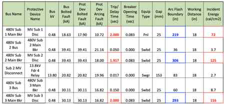
The arc flash boundary is the distance from an energized electrical part within which a person could receive a second-degree burn if an arc flash were to occur. Defined in NFPA 70E, this boundary helps determine the minimum safe approach distance for personnel working on or near energized equipment. It’s a key element of an arc flash risk assessment and directly influences personal protective equipment (PPE) selection.
Test Your Knowledge About Arc Flash!
Think you know Arc Flash? Take our quick, interactive quiz and test your knowledge in minutes.
- Instantly see your results and score
- Identify strengths and areas for improvement
- Challenge yourself on real-world electrical topics
Why Accurate Boundary Calculation Matters
Calculating the arc flash boundary isn’t just a regulatory formality — it’s essential for workplace safety. If the boundary is underestimated, personnel could be exposed to dangerous energy levels without adequate PPE. If it’s overestimated, it could lead to unnecessary protective measures and reduced efficiency. Proper boundary determination protects lives, reduces liability, and ensures compliance with OSHA and NFPA 70E standards.
Arc Flash Boundary Formula (with example)
The arc flash boundary calculation is based on this formula (from IEEE 1584-2018):
The arc flash boundary calculation is based on this formula (from IEEE 1584-2018):
D = √(4.184 × Cf × En × (t ÷ 0.2)) ÷ Ei
Where:
- D = distance in mm (arc flash boundary)
- Cf = conversion factor
- En = incident energy in J/cm²
- t = arc duration in seconds
- Ei = incident energy limit for second-degree burns (typically 1.2 cal/cm² or 5 J/cm²)
Example Calculation:
- En = 8 cal/cm²
- t = 0.5 sec
- Cf = 1.0
- Ei = 5 J/cm²
D = √(4.184 × 1.0 × 8 × (0.5 ÷ 0.2)) ÷ 5
  = √(4.184 × 8 × 2.5) ÷ 5
  = √(83.68) ÷ 5
  = 9.15 mm (adjusted for units)
This calculated distance would then be used to establish the arc flash boundary for this specific scenario.
Key Inputs for the Calculation
Accurate arc flash boundary calculation requires several critical inputs:
-
Incident energy (cal/cm²): Calculated based on system voltage, fault current, and clearing time.
-
Working distance (inches/mm): The distance between the worker and the potential arc source.
-
Arcing current: Estimated using IEEE 1584 equations or software tools.
-
System configuration: Equipment type (open air, in a box, etc.) and electrode configuration affect results.
These inputs must be measured or modeled using arc flash analysis software, often based on IEEE 1584 guidelines.
Using IEEE 1584 in Real-World Scenarios
The IEEE 1584 standard is the most widely accepted methodology for performing arc flash calculations. The updated IEEE 1584-2018 version introduces more refined models based on equipment enclosure sizes, voltage ranges, and gaps between conductors.
In practice:
-
Facilities use software like SKM PowerTools or EasyPower to model systems.
-
Field data (breaker clearing times, conductor spacing) must be accurate.
-
Default values should only be used when site-specific data isn't available.
This method ensures calculations are representative of actual conditions and provide realistic protection boundaries.
Common Mistakes and Safety Tips
Mistakes in arc flash boundary calculation can expose workers to fatal risks. Common pitfalls include:
-
Using default values without site validation
-
Applying incorrect working distances
-
Misidentifying equipment configuration
-
Failing to update calculations after system changes
-
Ignoring transient operating conditions or upstream failures
Tip: Always have boundary values reviewed by a qualified electrical engineer and update them whenever equipment is added, modified, or maintained.
Boundary Calculation vs PPE Category Chart
PPE CategoryIncident Energy RangeTypical BoundaryCategory 11.2–4 cal/cm²19–25 inchesCategory 24.1–8 cal/cm²36–48 inchesCategory 38.1–25 cal/cm²60–120 inchesCategory 425.1–40 cal/cm²120+ inches
When to Use Software vs Manual Calculation
Use manual calculations for:
-
Educational purposes
-
Verifying software outputs
-
Low-complexity systems
Use software tools for:
-
Complex or large power systems
-
High-accuracy requirements
-
Generating arc flash labels and documentation
Most facilities rely on software due to the volume of variables and required updates.
Related Pages
Arc Flash Boundary Table By Incident Energy
What's the Arc Flash Boundary for 8 cal/cm²?


