Limited Approach Boundary Defined

Arc Flash Training CSA Z462 - Electrical Safety Essentials
Our customized live online or in‑person group training can be delivered to your staff at your location.

- Live Online
- 6 hours Instructor-led
- Group Training Available
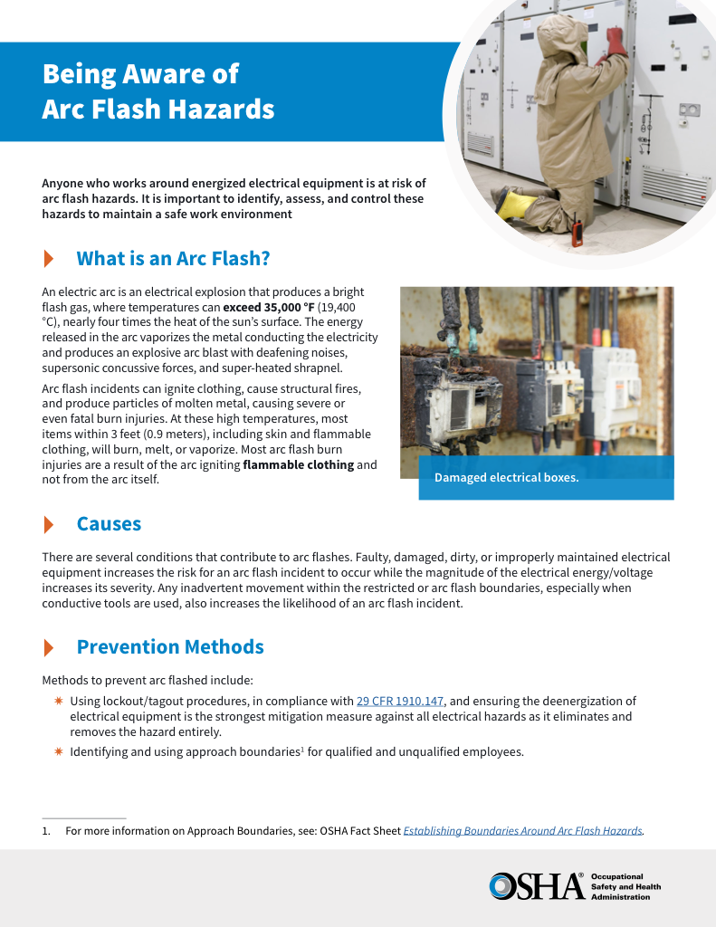
Download Our OSHA 4475 Fact Sheet – Being Aware of Arc Flash Hazards

- Identify root causes of arc flash incidents and contributing conditions
- Apply prevention strategies including LOTO, PPE, and testing protocols
- Understand OSHA requirements for training and equipment maintenance
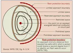
The Limited Approach Boundary defines the distance from energized parts where shock protection becomes mandatory. Based on system voltage, this NFPA 70E-defined zone determines when PPE, qualified supervision, and safety planning are required for safe electrical work.
What Is the Limited Approach Boundary?
It is a shock protection zone set at a specific distance from an exposed energized part. It is designed to limit the likelihood of accidental contact or electrical arc-related shock when performing tasks near energized components.
✅ Defines minimum safe distance for workers
✅ Protects against electrical shock hazards
✅ Ensures compliance with OSHA and NFPA 70E standards
Visit Our NFPA 70E Training Course
Visit Our Our CSA Z462 Training Course
This boundary is not about thermal energy like the Arc Flash Boundary, but focuses on voltage potential and human proximity. If you cross this line, you enter an area with an increased risk of electric shock. For quick visual guidance, our Arc Flash Boundary Chart provides a clear and easy-to-read illustration of the required approach limits and protective measures.
When a shock hazard exists near energized electrical equipment, only qualified workers trained under National Fire Protection guidelines should perform the task. Without proper precautions, contact with live parts can result in severe burns or even death. To reduce risk, employers must enforce strict safety protocols and ensure that personal protective equipment (PPE) is worn at all times, providing a critical barrier between workers and dangerous energy sources.
How Is the Limited Approach Boundary Determined?
The boundary is based on system voltage. For example:
-
50V to 150V: 3 feet, 6 inches (1.07 meters)
-
151V to 750V: 3 feet, 6 inches (1.07 meters)
-
751V to 15kV: 5 feet (1.52 meters)
For detailed comparisons of voltage thresholds and distances, see our Arc Flash Boundary Table by Incident Energy.
FREE EF Electrical Training Catalog
Download our FREE Electrical Training Catalog and explore a full range of expert-led electrical training courses.

- Live online and in-person courses available
- Real-time instruction with Q&A from industry experts
- Flexible scheduling for your convenience
These distances are determined using standardized shock hazard equations and are listed in NFPA 70E Annex C.
Practical Workplace Implications
Crossing the Limited Approach Boundary isn't prohibited — but it triggers specific safety requirements:
-
Only qualified personnel may cross unaccompanied
-
A qualified person must continuously escort unqualified workers
-
A shock risk assessment must be completed beforehand
-
Workers must wear appropriate voltage-rated gloves and tools
This boundary often marks the start of the decision-making zone, where PPE becomes mandatory and Lockout/Tagout protocols must be implemented.
If work is to be performed closer than this boundary, it often overlaps with or leads into the Restricted Approach Boundary, which involves even stricter controls.
Shock Hazard Analysis and Compliance Requirements
A shock hazard analysis or shock risk assessment is required whenever workers approach energized parts, ensuring that the safe approach distance for electrical work is clearly defined and understood. NFPA 70E outlines these limits in the arc flash approach boundaries NFPA 70E table / Annex C, which specifies the exact electrical shock protection distance based on system voltage. Employers must implement a formal arc flash risk assessment procedure to classify hazards into proper electrical hazard prevention categories, guiding the selection of PPE and work practices. Without this analysis, workers face a significantly higher risk of accidental contact, which could result in severe injury or death.
Crossing from the limited approach distance to the restricted approach distance requires higher levels of worker qualification, meaning only a qualified electrical worker trained in NFPA 70E may proceed. At this point, OSHA and NFPA standards mandate the use of voltage-rated tools and gloves, along with insulated equipment, to provide effective electrical contact prevention. In many cases, an energized electrical work permit (EEWP) must also be issued, documenting the justification for energized work, the hazards present, and the controls in place to mitigate these hazards. These requirements emphasize the crucial role of arc flash training, supervision, and planning in establishing a safe environment around live electrical systems.
Limited vs Arc Flash Boundary
It’s common to confuse the Limited Approach Boundary (LAB) with the Arc Flash Boundary (AFB). Here’s how they differ:
-
LAB: Focuses on shock hazards, measured by voltage
-
AFB: Focuses on thermal hazards, measured in cal/cm²
Both can exist in the same workspace but are based on separate risk types. For a full breakdown, visit our guide on What Is an Arc Flash Boundary.
Related Safety Zones
Understanding where the Limited Approach Boundary sits in context can help clarify the full protective strategy. These include:
-
Restricted Approach Boundary: A Tighter zone requiring insulated tools and elevated qualifications
-
Prohibited Approach Boundary: Now deprecated, once treated as equivalent to direct contact
-
Arc Flash Boundary Chart: A Visual aid comparing all boundary distances
Each plays a role in defining the total safe working environment. Electricians can reference our detailed Arc Flash Boundary Table By Incident Energy to understand safe working distances based on calculated incident energy levels.
Training and Labeling Requirements
Within the Limited Approach Boundary, electrical equipment must be labelled to indicate all applicable boundaries, including the LAB. Workers should receive training through certified programs that teach how to identify, assess, and respond to these shock protection zones. Our Arc Flash Boundary Calculation page explains how these distances are determined.
For workplace-specific assessments, use the 8 cal/cm² PPE threshold example outlined on our Arc Flash Boundary for 8 cal/cm² page.
Related Pages


