Arc Flash
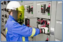
Electrical Safety Work Explained
Download Our FREE Arc Flash Handbook
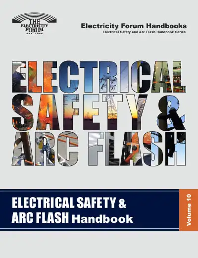
This edition continues our commitment to providing essential knowledge and best practices for safeguarding electrical professionals and maintaining safety standards in high-risk environments. As electrical systems become increasingly complex and the demand for higher power capacities grows, the importance of addressing electrical hazards—particularly arc flash risks—has never been more critical.
In this volume, we explore the latest advancements in electrical safety, focusing on strategies to mitigate the dangers of arc flash incidents and ensure the protection of workers in the field. From updated standards and regulations to innovative protective equipment and advanced risk assessment techniques, this handbook is designed to help professionals stay informed and equipped to prevent electrical accidents.
Through expert insights, case studies, and practical safety solutions, Volume 10 provides a comprehensive guide to minimizing risks, enhancing safety protocols, and fostering a culture of safety in electrical environments. Whether you're an electrical engineer, safety officer, or technician, this handbook serves as an invaluable resource for creating safer workplaces and improving the overall safety of electrical operations. Join us as we continue to advance the standards for electrical safety and arc flash prevention in this ever-evolving field.
Collections of the articles on electrical safety and arc flash in particular including a review of OSHA’s new electric power generation, transmission, and distribution and electrical protective equipment standards.
Latest Arc Flash Articles
Low Voltage Certification Explained

Electrical Safety Certification Explained
Arc Flash Calculator - Incident Energy
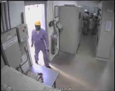
Arc Flash Video