Arc Flash Boundary Chart - Safe Approach Distances
By R.W. Hurst, Editor
NFPA 70e Training - Arc Flash
Our customized live online or in‑person group training can be delivered to your staff at your location.
- Live Online
- 6 hours Instructor-led
- Group Training Available
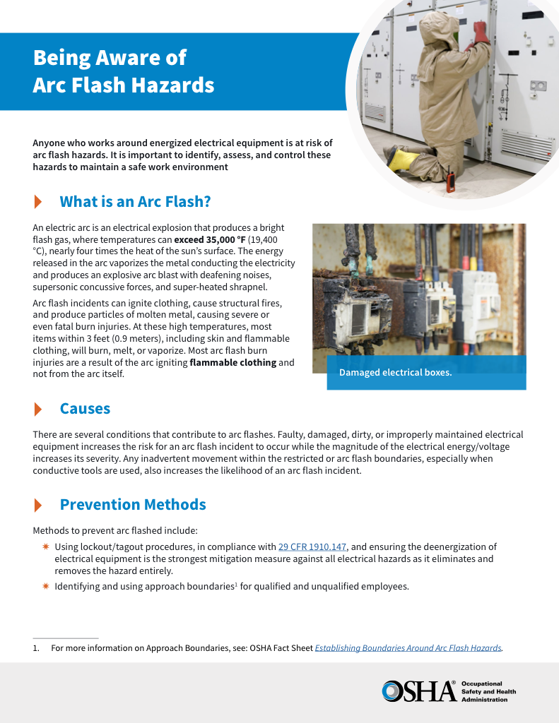
Download Our OSHA 4475 Fact Sheet – Being Aware of Arc Flash Hazards
- Identify root causes of arc flash incidents and contributing conditions
- Apply prevention strategies including LOTO, PPE, and testing protocols
- Understand OSHA requirements for training and equipment maintenance
An Arc Flash Boundary Chart outlines the minimum safe distance from energized equipment where a person could be exposed to a thermal incident. This boundary is defined by NFPA 70E and helps determine the required PPE level to reduce the risk of injury.
Request a Free Training Quotation
What is an Arc Flash Boundary Chart?
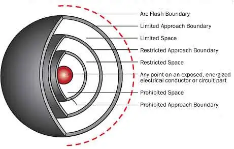
An Arc Flash Boundary Chart is a visual safety reference that outlines critical zones around energized electrical equipment where workers face potential thermal exposure from an arc flash event. These zones are defined by the amount of thermal energy, known as incident energy, that could be released during an electrical explosion. The boundary distance is typically measured in calories per square centimetre (cal/cm²) and directly influences the level of protection required.
✅ Establishes Protection Zones – The chart identifies threshold distances where arc flash hazards begin, helping planners designate safe work limits around equipment.
✅ Supports Risk Assessment – It assists safety professionals in evaluating job site hazards and determining when additional safety controls or energized work permits are required.
✅ Promotes Standardized Safety Practices –The chart helps enforce consistent protection measures across facilities by referencing NFPA 70E and CSA Z462 guidelines.
Each boundary distance shown in the chart corresponds to a specific incident energy exposure level. The farther a worker is from the source, the less energy they are exposed to, meaning reduced PPE requirements. Conversely, close proximity to energized equipment demands more robust arc-rated protective gear.
The arc flash boundary is sometimes called the “protection boundary” or “minimum safe approach distance.” This distance must be calculated individually for each piece of electrical equipment, based on its configuration, voltage level, and available fault current. The boundary is not fixed; it can vary widely between systems, making accurate analysis essential.
Test Your Knowledge About Arc Flash!
Think you know Arc Flash? Take our quick, interactive quiz and test your knowledge in minutes.
- Instantly see your results and score
- Identify strengths and areas for improvement
- Challenge yourself on real-world electrical topics
Using an Arc Flash Boundary Chart as part of a comprehensive electrical safety strategy ensures that hazard zones are clearly marked, appropriate PPE is used, and only properly trained personnel enter high-risk areas. When integrated with energy assessments and worker training, the chart becomes a practical tool for minimizing injuries and meeting regulatory safety standards.
To delve deeper into the specifics of boundaries, consult our article on Arc Flash Boundary.
Sample Arc Flash Boundary Chart
| System Voltage | Available Fault Current (kA) | Clearing Time (s) | Incident Energy (cal/cm²) | Arc Flash Boundary (AFB) |
|---|---|---|---|---|
| 208V | 15 | 0.1 | 1.5 | 18 inches (1.5 ft) |
| 480V | 10 | 0.1 | 2.8 | 36 inches (3 ft) |
| 600V | 25 | 0.2 | 8.0 | 60 inches (5 ft) |
| 480V | 35 | 0.5 | 12.0 | 96 inches (8 ft) |
| 13.8kV | 5 | 0.1 | 4.0 | 48 inches (4 ft) |
What are AF Boundaries?
The protection zone is the minimum safe distance from energized equipment that an unqualified worker can approach without wearing personal protective equipment (PPE). The NFPA 70E and CSA Z462 standards guide the minimum distances that should be maintained between energized electrical equipment and workers based on the incident energy levels.
Three protection boundaries are defined by the NFPA 70E and CSA Z462 standards:
Limited Approach Boundary (LAB)—The LAB is the minimum distance from the energized equipment that an unqualified person can approach. This zone is generally marked with a yellow line and is intended to prevent unqualified personnel from entering the hazard zone.
Restricted Approach Boundary (RAB) - The RAB is the minimum distance from the energized equipment a qualified worker can approach without wearing the appropriate PPE. This zone is marked with a red line indicating where a worker must begin wearing the appropriate PPE to prevent injury.
Prohibited Approach Boundary (PAB) - The PAB is the closest distance to the energized equipment considered safe for any person to approach, regardless of PPE. This zone is marked with a black line and indicates the most hazardous area.
What is the Minimum Arc Flash Boundary?
The minimum arc flash boundary is determined by the incident energy level that could be released during an electrical explosion. The incident energy level is calculated using complex mathematical formulas that consider the system voltage, available fault current, and the time it takes for the protective devices to clear the fault.
The NFPA 70E and CSA Z462 standards provide tables and formulas to help calculate the incident energy and the minimum distance. The minimum approach distance is the distance from the energized equipment where the incident energy is below 1.2 cal/cm², which is the level of thermal energy that can cause second-degree burns to unprotected skin. For a breakdown of boundary distances by energy level, refer to our Arc Flash Boundary Table by Incident Energy.
What is the Arc Flash Boundary for 480V?
The protection zone for 480V arc flash equipment can vary depending on the incident energy level. However, the NFPA 70E and CSA Z462 standards provide a table that specifies the minimum distance for 480V equipment based on the available fault current and the clearing time of the protective device.
For example, if the available fault current is 10,000 A and the protective device clearing time is 0.1 seconds, the minimum approach distance for 480 V equipment is 3 feet for a Category 1 PPE level. If you’re working with high-risk levels like 8 cal/cm², see What Is the Arc Flash Boundary for 8 cal/cm²? to ensure proper distance and PPE selection.
It's important to note that the minimum approach distance can vary depending on several factors, including system voltage, available fault current, and protective device settings. Therefore, it's essential to accurately calculate the proper working distance for each piece of equipment to ensure that workers are adequately protected.
How the Arc Flash Boundary Chart Is Used in the Field
The chart serves as a visual reference, enabling safety managers, engineers, and qualified electrical workers to determine safe working distances based on incident energy levels quickly. Typically, the chart displays boundary distances for various voltages, fault clearing times, and working distances. It’s used during risk assessments and job planning to determine the safe distance personnel can be positioned from energized equipment without exceeding the 1.2 cal/cm² threshold. By consulting the chart, professionals can select the appropriate PPE and ensure that labelling and signage accurately reflect the hazard zones. Learn more about Incident Energy and how it affects arc flash risk and PPE requirements.
FREE EF Electrical Training Catalog
Download our FREE Electrical Training Catalog and explore a full range of expert-led electrical training courses.

- Live online and in-person courses available
- Real-time instruction with Q&A from industry experts
- Flexible scheduling for your convenience
How to Calculate Boundaries
The chart can be used to calculate the minimum approach distance, but it requires an understanding of the electrical system and its potential hazards. The process involves a detailed analysis of the electrical system and the potential fault currents that could occur.
The NFPA 70E and CSA Z462 standards outline the calculation of the protection zone using various methods, including the incident energy analysis method and the PPE category method.
The incident energy analysis method involves conducting a detailed analysis of the electrical system to determine the potential incident energy levels at various points within the system. This method requires complex calculations and detailed information about the system components, such as the available fault current and protective device settings.
The PPE category method determines the minimum PPE level required for a specific task based on the incident energy level. This method involves using tables to determine the required Personal Protective Equipment (PPE) level for a specific incident energy level and selecting the appropriate PPE based on the task.
Regardless of the method used, accurately calculating this safe distance is critical to ensuring adequate worker safety.
Can an Unqualified Person Cross the AFB?
An unqualified person should never cross the LAB of an energized piece of electrical equipment. The LAB is the minimum distance from the energized equipment that an unqualified person can approach, and it's intended to keep unqualified personnel from entering the hazard zone.
Only a qualified electrical worker who has received specialized training and is authorized to work on or near energized electrical equipment should cross the RAB. Crossing the RAB without appropriate PPE is dangerous and can result in severe burns, injuries, or even death.


