VFD Variable Frequency Drive
By Paul Wright, P.Eng.
By Paul Wright, P.Eng.
Our customized live online or in‑person group training can be delivered to your staff at your location.


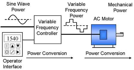
A VFD Variable Frequency Drive controls AC motor speed and torque by adjusting voltage and frequency. They improve motor efficiency, ensure drive performance, and reduce energy consumption in industrial, commercial, and HVAC applications.
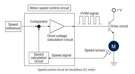
A modern AC drive, also known as an adjustable frequency drive or variable speed drive, allows operators to control the speed of motors by varying the frequency and voltage supplied to the motor windings. At the core of a frequency drive VFD are power electronics such as the insulated gate bipolar transistor (IGBT), which switch rapidly using pulse width modulation (PWM) techniques to deliver precise control. These technologies enable variable frequency drives (VFDs) to optimize performance, reduce mechanical stress, and save energy across industrial and commercial systems. By fine-tuning motor operation, an AC drive extends equipment life and enhances efficiency, making it one of the most effective tools for modern motor management.
Electric Motor Testing Training
Request a Free Training Quotation
When you start an induction motor directly on line power, it pulls a surge of current because the motor is “standing still” while the supply is trying to drive it at full speed. This sudden demand creates a locked rotor current, many times higher than the normal operating current.
Starting an AC motor across the line causes a high locked rotor current to flow due to the difference between the stator rotating field and the rotor rotating field. At the initial start point, the two frequencies have a 100% difference, requiring the lock rotor current to flow (Figure 1, left chart). As the rotor speed increases, the difference between the two frequencies decreases, and the current begins to fall. It does not reach full load current until the rotor speed approaches the rated speed.
Stay informed with our FREE Motors and Drives Newsletter — get the latest news, breakthrough technologies, and expert insights, delivered straight to your inbox.
By contrast, a VFD starts at the rated slip frequency (2–3 Hz), enabling the rotor to produce constant torque with full-load current. As the drive frequency rises, the voltage proportionally increases, maintaining the rated motor flux at all speeds. (Figure 1, right chart). As the drive frequency increases, the voltage proportionally rises, maintaining rated motor flux and torque across the speed range.
The VFD can produce 100%, 125%, or even 200% of the rated torque at corresponding current levels, up to approximately 80% of the motor’s breakdown torque. Beyond that point, the current rises rapidly.
Figure 1: Current and torque characteristics for across-the-line starting versus VFD control.
Practical Tip: Using VFDs reduces mechanical stress on motors and connected equipment during startup, extending equipment life while improving energy efficiency.
The weakest link in a variable frequency drive is often the DC bus capacitors, rated between 950–1100 VDC. Units below 1000 VDC generally have shorter service lives. Proper specifications for VFD sizing can extend reliability and reduce failures.
To mitigate this, specifications for 575-volt VFDs should be written in either of the following ways:
The VFD should be capable of continuous operation with a line voltage up to 15% above the motor’s rated voltage (575V +15%).
The drive shall operate continuously from three-phase RMS line voltages ranging from the motor’s rated voltage to 650 volts.
Practical Tip: Specifying higher-quality capacitors and ensuring adequate cooling will improve drive performance, reduce failures, and increase service life.
When using a three-phase rated VFD on single-phase power, the unit must be oversized because single-phase current is 1.732 times higher than the motor’s three-phase rating. Properly matching the electric motor design with the drive is essential for safe conversion and performance. The solution is to size the drive at roughly double the motor’s full load amps (FLA).
For example, a 10 HP, 25.5-ampere three-phase motor at 230 VAC on a single-phase 208 V supply requires a VFD with a continuous output capacity of at least 51 amps. However, since the VFD can only output 193 V three-phase at 208 V, a step-up transformer (208 V to 240 V) is required to maintain voltage within the motor’s ±10% tolerance.
Practical Tip: Always verify both current and voltage requirements when converting from single-phase to three-phase with VFDs to avoid derating motor performance.
VFDs are nonlinear loads that distort current waveforms. For three-phase units, harmonics occur at 6n ± 1 (5th, 7th, 11th, 13th, …). For single-phase units, they occur at 4n ± 1 (3rd, 5th, 7th, 9th, …). This distortion affects overall motor performance and power quality.
Harmonics can be analyzed with the Fourier transformation, which breaks distorted waveforms into sums of pure sine waves. Mitigation strategies include line reactors, harmonic filters, or advanced rectifier designs.
For three-phase VFDs (six rectifiers), harmonics occur at 6n ± 1 (5th, 7th, 11th, 13th, 17th, 19th …).
For single-phase VFDs (four rectifiers), harmonics occur at 4n ± 1 (3rd, 5th, 7th, 9th, 11th …).
Figure 2: Odd Harmonics signals superimposed, 1st, 3rd, 5th, 7th, 9th, 11th and 13th
Figure 3: Current Waveform and the Fourier Harmonic Breakdown
The French mathematician Fourier demonstrated that distorted waveforms can be expressed as the sum of many sine waves of different frequencies and magnitudes, a concept now known as the Fourier transformation.
Practical Tip: Harmonic distortion can be mitigated with line reactors, harmonic filters, or 12-pulse rectifier designs to protect power quality and improve motor efficiency.
The above odd harmonics, with the inverse for their magnitude being added, will make a pure square sine wave if we add all the odd harmonics together. A mathematician named Fourier developed a relationship between a non-sinusoidal signal and a series of pure sine waves of different magnitudes to represent the distorted waveform. This is known as the Fourier transformation.

NEMA motors are rated slightly below system voltage to account for real-world voltage drops. Since torque output is proportional to voltage squared, a 5% reduction in voltage results in a torque reduction of approximately 10%. Proper motor overload protection ensures reliability across varying supply conditions.
Practical Tip: Always verify nameplate ratings against the supply voltage to ensure optimal motor efficiency and drive performance.
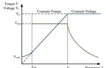
Figure 4: How motor torque and performance vary with system voltage.
Why does the VFD seem to behave differently when it is operated on the standby generator?
Generators have higher impedance and weaker frequency regulation compared to utility power. The rapid response of a VFD in motor control can conflict with the slower response of the generator, resulting in instability, surges, and distorted voltage waveforms. Adjusting VFD programming (e.g., acceleration and deceleration times) can improve stability when operating on backup power systems.
The second issue is that generator impedance amplifies harmonic distortion. This flattens voltage waveforms at the VFD terminals, affecting not only the drive but all connected loads.
Practical Tip: Increasing VFD acceleration and deceleration times, as well as using filters, can help reduce instability when operating drives on standby generators.
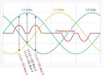
Figure 5: VFD interaction with generator impedance and resulting waveform distortion.
Understanding electric motors and drives is critical for optimizing system efficiency and reliability. VFDs enhance synchronous motors, variable frequency drive in HVAC systems, and industrial applications, but they require correct VFD training and specification.
Advantages To Instructor-Led Training – Instructor-Led Course, Customized Training, Multiple Locations, Economical, CEU Credits, Course Discounts.
Request For QuotationWhether you would prefer Live Online or In-Person instruction, our electrical training courses can be tailored to meet your company's specific requirements and delivered to your employees in one location or at various locations.