Short Circuit Current Calculation Explained
By Colin P. Hurst, Associate Publisher
By Colin P. Hurst, Associate Publisher
Our customized live online or in‑person group training can be delivered to your staff at your location.
Short circuit current calculation determines the maximum electric current that can flow during a fault. It’s essential for sizing protective devices, ensuring system safety, and preventing equipment damage. Factors include voltage, impedance, transformer rating, and conductor length.
This critical process enables electrical professionals to determine the magnitude of currents that can occur during fault conditions, which in turn helps them design protective measures to prevent system failures. Knowing how to perform a SCCC enables engineers and electricians to select the appropriate protective devices, minimize potential damage, and reduce downtime in both industrial and commercial environments. This vital skill not only safeguards equipment but also improves overall system performance and efficiency. Understanding how to read nominal voltage is essential for anyone working with electrical systems, especially when evaluating safe operating levels.
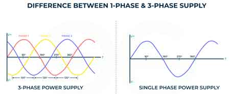
A short circuit (S/C) occurs when an unintended path with very low resistance is created in an electrical circuit. This can be caused by various factors, such as insulation failure, loose connections, or accidental contact between conductors. The sudden drop in impedance leads to a dramatic increase in current flow, potentially causing significant damage to equipment and posing serious safety hazards, including fires and electric shock. In industrial and commercial environments, S/Cs can result in costly downtime, equipment failure, and even risks to human safety. As such, understanding how to predict and mitigate the effects of S/Cs through accurate measurements is fundamental to electrical engineering. Our electrical training programs help professionals master key concepts like single-phase power, voltage drop, and system design.
Download our FREE Electrical Training Catalog and explore a full range of expert-led electrical training courses.

| Parameter | Low Voltage System | Medium/High Voltage System | Notes |
|---|---|---|---|
| Voltage Level | Less than 1,000 volts | Greater than 1,000 volts | Defines equipment class and calculation complexity |
| Primary Components | Transformers, panelboards, circuit breakers | Generators, transformers, switchgear, relays | Equipment affects fault current magnitude and duration |
| Impedance Source | Transformer impedance primarily | System-wide impedance (including lines and sources) | Total impedance determines fault current |
| Transformer Data Required | kVA rating, impedance percentage, voltage | Same, plus X/R ratio for accuracy | Manufacturer data needed |
| Conductor Impedance | Often neglected or simplified | Must be included for accuracy | Affects overall fault current level |
| X/R Ratio Impact | Minimal impact | Significant impact | Influences peak fault current and breaker selection |
| Calculation Tools | Manual, spreadsheet, lookup tables | Advanced software (ETAP, SKM, EasyPower) | High voltage systems require modelling tools |
| Typical Applications | Commercial buildings, light industrial facilities | Substations, utilities, large industrial sites | Affects safety and design standards |
| Protective Device Sizing | Circuit breakers, fuses | Relays, reclosers, current transformers (CTs) | Devices must be rated for worst-case fault conditions |
Accurately calculating the short circuit current is crucial for several reasons:
Protective devices, such as fuses and circuit breakers, must be capable of safely interrupting faults. Their interrupting rating must exceed the maximum possible short-circuit (S/C) current at their installation point to prevent equipment damage and ensure operator safety. Electrical equipment, including cables, transformers, and switchgear, must be designed to withstand the thermal and mechanical stresses generated by a short-circuit (S/C). Precise measurements ensure that equipment is rated properly to avoid catastrophic failure. Accurate analysis of system load and balance can be aided by tools such as the electrical load calculator and phase angle calculator.
High S/C currents can affect the stability of the entire electrical system, causing voltage dips, equipment malfunctions, or damage. Accurate calcs help identify areas of potential vulnerability, allowing for the implementation of corrective measures, such as adjusting protection settings or upgrading equipment. Short-circuit current calculations are also necessary for compliance with electrical codes and standards, such as the National Electrical Code (NEC) and IEEE standards. Engineers designing protection schemes should understand the implications of short-circuit current calculations and the risks associated with using 8A and 10A fuses in parallel.
Several factors influence the magnitude of the S/C current. Understanding these variables is essential to performing accurate measurements:
The impedance of the power source, whether it’s a utility grid or a generator, significantly impacts the fault. A lower source impedance results in a higher S/C current, making it essential to evaluate this parameter during system design. Transformers play a crucial role in limiting S/C currents. The transformer impedance is typically expressed as a percentage, and a higher percentage impedance results in a lower fault current on the secondary side. Accurate modelling of transformer parameters is key to determining short circuits on both the primary and secondary sides of the transformer.
The impedance of cables and busbars connecting various components in the circuit also contributes to the overall system impedance. Longer cables or those with higher resistance will lower the S/C current, while shorter, thicker cables with lower resistance allow for higher currents during faults. Motors, especially large induction motors, can contribute significantly to S/C currents during the initial moments of a fault. This motor contribution is often transient but must be included in the estimation, as neglecting it can lead to underestimating faults and improperly sizing protective devices.
The location of the fault within the system plays a significant role in determining the magnitude of the short-circuit (S/C) current. Faults closer to the power source generally produce higher S/C currents due to the reduced impedance between the fault and the source. From power system engineering to interpreting a three-phase bus line diagram, our resources support both design and troubleshooting tasks.
Various methods are employed to calculate the short-circuit current, ranging from simplified approaches to more complex analysis techniques. One common method involves using Ohm’s Law:
Isc = V / Z
Where:
Isc is the short circuit current, V is the system voltage, and Z is the total impedance of the circuit from the source to the fault location.
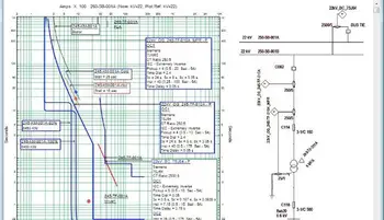
The total impedance (Z) includes the impedance of the source, transformer, cables, and any other components in the current path. However, in modern electrical systems, more sophisticated software tools are often used to automate SCCCs, particularly in complex systems where manual figuring may be cumbersome or prone to error.
Stay informed with our FREE Electrical Engineering Newsletter — get the latest news, breakthrough technologies, and expert insights, delivered straight to your inbox.
When calculating the short-circuit current on the secondary side of a transformer, it's essential to consider the transformer's impedance. The formula can be modified as follows:
Isc (secondary) = (V (secondary) / Z (transformer)) * 100 / %Z
Where:
Isc (secondary) is the short circuit current on the secondary side of the transformer, V (secondary) is the secondary voltage of the transformer, Z (transformer) is the transformer impedance in ohms, and %Z is the transformer impedance expressed as a percentage.
This calculation is crucial in determining the fault that protective devices on the secondary side of a transformer must be able to handle. It ensures that circuit breakers, fuses, and other protective elements are correctly sized and rated.
In addition to manual determinations, electrical engineers increasingly rely on advanced simulation tools to model S/C scenarios. These tools can account for complex system configurations, varying load conditions, and different types of faults, providing a more accurate and comprehensive analysis. By utilizing software, professionals can simulate fault conditions under various operational scenarios, enabling better contingency planning and more informed decision-making during system design.
SCCC is an essential practice in electrical engineering that ensures the safe and reliable operation of electrical systems. By understanding the factors that influence faults and employing accurate determination methods, electrical professionals can ensure the proper selection of protective devices, protect equipment from damage, and maintain the stability of the electrical system. Moreover, the use of advanced tools and techniques enhances the precision of these estimations, ultimately contributing to the overall safety, efficiency, and reliability of modern electrical infrastructure.
Explore 50+ live, expert-led electrical training courses –