Phase Angle Calculator
By Howard Williams, Associate Editor
By Howard Williams, Associate Editor
Our customized live online or in‑person group training can be delivered to your staff at your location.
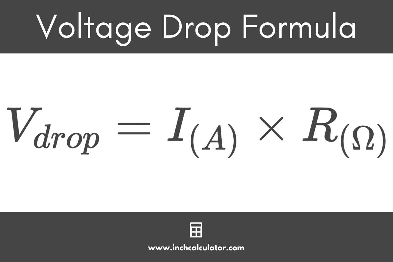
A Phase Angle Calculator helps analyze AC circuits by determining the angular difference between voltage and current. It supports electrical engineering, power factor correction, impedance analysis, and efficient system design in industrial, utility, and academic applications.
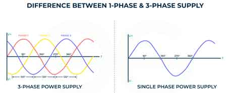
It's is an essential tool for industrial electricians to accurately measure and analyze the relationship between voltage and current in AC electrical systems. Understanding angles is crucial for ensuring optimal power factor, minimizing energy waste, and enhancing the efficiency of electrical equipment. Let's examine how a phase angle calculator works, its practical applications, and why mastering this concept is crucial for troubleshooting electrical issues, optimizing system performance, and supporting energy-saving initiatives in industrial environments. Electricians will gain valuable insights into calculating angles, interpreting results, and applying this knowledge to real-world electrical systems. To fully understand how it works, electricians often review the basics of what is single-phase power to see how phase relationships develop in AC systems.
A phase shift analyzer operates by analyzing the circuit's impedance components, including resistance, inductance, and capacitance. The calculator determines the shift using the arctangent function by inputting relevant values, such as the resistive load and reactance. This calculation not only aids in understanding circuit behaviour but also helps identify mismatches in system design that could lead to inefficiencies or malfunctions. Modern calculators often feature user-friendly interfaces, making them accessible to both seasoned engineers and students. Accurate phase angle calculations are crucial in power system analysis and design, where engineers evaluate system stability, load flow, and efficiency.
There are various types of analyzers available, each tailored for specific applications. Some are standalone devices designed for field use, while others are integrated into advanced testing equipment. Engineers use these tools in diverse settings, from evaluating power systems in industrial plants to troubleshooting electrical issues in residential setups. For instance, when aligning generators or synchronizing multiple power sources, accurate angle calculations ensure seamless operation and prevent costly disruptions.

When electrical problems arise, a shift analyzer becomes a diagnostic asset. It enables engineers to pinpoint issues such as imbalanced loads, faulty connections, or deviations in power factor. By identifying anomalies in the shift, the tool facilitates targeted interventions, reducing downtime and improving system reliability. This functionality is particularly valuable in industries where an uninterrupted power supply is critical, such as data centers and manufacturing facilities. When working with multi-phase systems, understanding phase-to-phase connection and phase rotation meter principles ensures accurate angle measurements and prevents costly errors.
Working with AC systems involves inherent risks, particularly when dealing with high voltages. Proper safety protocols must be followed to ensure the safe use of a shift analyzer. Always verify that the Phase Angle Calculator and its accessories are rated for the voltage level of the system being analyzed. Use insulated tools and wear appropriate personal protective equipment (PPE). Additionally, ensure the calculator is calibrated regularly to maintain accuracy and reliability.
In practical scenarios, a phase shift analyzer is used to enhance the performance of various electrical systems. For example, it plays a pivotal role in designing HVAC systems, optimizing motor operations, and balancing transformer loads. By ensuring accurate alignment, these calculators prevent equipment damage and extend the lifespan of critical components. Their versatility and ease of use make them an essential tool for professionals in the electrical and engineering fields.
From diagnosing electrical issues to optimizing power efficiency, the Phase Angle Calculator enables engineers to make informed decisions and ensure system integrity. By adhering to safety guidelines and leveraging the calculator’s capabilities, professionals can ensure the reliability and efficiency of electrical systems in diverse applications. This equipment is invaluable for troubleshooting and ensuring that electrical systems are operating optimally. By using a shift analyzer, electricians can improve the accuracy of their diagnostics, enhance the reliability of electrical installations, and prevent costly operational disruptions. Ultimately, it contributes to the overall safety and performance of electrical systems. For in-depth studies, combining a phase angle calculator with related tools, such as the electrical load calculator or DC voltage drop calculation, helps professionals achieve precise system performance and energy efficiency.
To calculate the phase angle in an AC electrical system, you need to understand the relationship between the voltage and current waveforms. The angle (θ) represents the shift in degrees between these two waveforms. It is typically measured using an angle calculator or by applying trigonometric functions. The calculation requires knowing the values of the resistive (R) and reactive (X) components in the circuit. The angle can be calculated using the arctangent (tan⁻¹) of the ratio of the reactance (X) to the resistance (R), as shown in the formula:
θ = tan⁻¹(X / R)
The formula for the phasor angle, often referred to as the angle, is derived from the components of impedance (Z) in an AC circuit. The impedance has two components: the resistive component (R) and the reactive component (X), which can be either inductive (XL) or capacitive (XC). The phasor angle (θ) is calculated using the following trigonometric formula:
θ = tan⁻¹(X / R)
Where:
θ is the phasor or phase angle in degrees.
X is the total reactance of the circuit (inductive reactance XL or capacitive reactance XC).
R is the resistance of the circuit.
The angle tells you whether the current is leading or lagging the voltage. A positive phase angle indicates lagging (typical for inductors), while a negative angle indicates leading (typical for capacitors).
The phase angle of an inductor is calculated based on the relationship between the inductive reactance (XL) and the resistance (R) in the circuit. Since an inductor causes the current to lag behind the voltage by 90 degrees in a purely inductive circuit, the shift can be calculated if the circuit also has resistive components. The angle (θ) is calculated using the formula:
Stay informed with our FREE Electrical Engineering Newsletter — get the latest news, breakthrough technologies, and expert insights, delivered straight to your inbox.
θ = tan⁻¹(XL / R)
Where:
θ is the phase angle in degrees.
XL is the inductive reactance, calculated as XL = 2πfL, where f is the frequency and L is the inductance in henries.
R is the resistance of the circuit.
If the circuit is purely inductive (no resistance), the angle will be 90 degrees, indicating maximum lag. However, in real-world applications, circuits usually have both resistance and inductance, so the angle will be less than 90 degrees.
The phase angle can also be calculated using the power factor (PF) of the circuit. Power factor represents the cosine of the angle between the current and voltage waveforms. The power factor is a dimensionless value between 0 and 1, where 1 represents a perfectly in-phase system. To calculate the angle (θ) from the power factor, use the following formula:
θ = cos⁻¹(PF)
Where:
θ is the phase angle in degrees.
PF is the power factor (a decimal value between 0 and 1).
For example, if the power factor is 0.8, the angle is calculated as:
θ = cos⁻¹(0.8) ≈ 36.87°
This method is widely used in power quality analysis and system optimization, as power factor correction is often necessary to reduce phase angle and improve energy efficiency.
Electrical Engineering Channel
Advantages To Instructor-Led Training – Instructor-Led Course, Customized Training, Multiple Locations, Economical, CEU Credits, Course Discounts.
Request For QuotationWhether you would prefer Live Online or In-Person instruction, our electrical training courses can be tailored to meet your company's specific requirements and delivered to your employees in one location or at various locations.