Three-Phase Bus Line Diagram Explained
Arc Flash Analysis/Study
Our customized live online or in‑person group training can be delivered to your staff at your location.
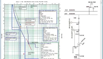
- Live Online
- 12 hours Instructor-led
- Group Training Available
Download Our OSHA 3875 Fact Sheet – Electrical PPE for Power Industry Workers
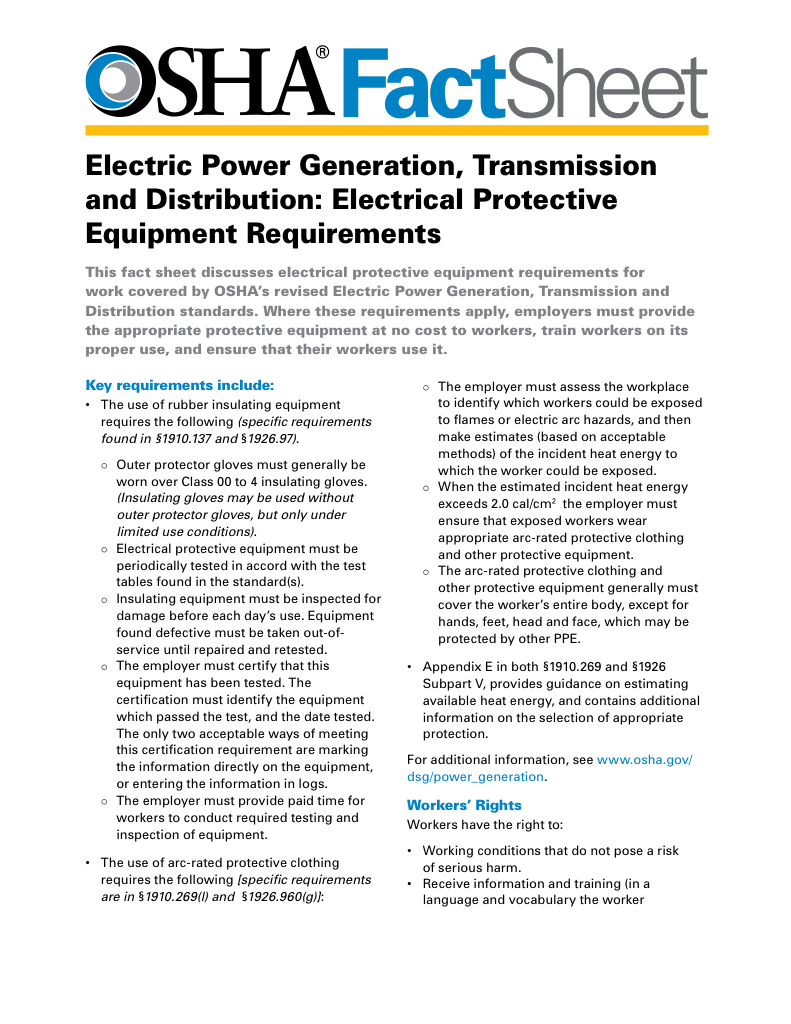
- Follow rules for rubber gloves, arc-rated PPE, and inspection procedures
- Learn employer obligations for testing, certification, and training
- Protect workers from arc flash and electrical shock injuries
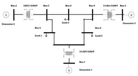
Three Phase Bus Line Diagram illustrates busbars, feeders, and switchgear in a three-phase system, using single-line schematics for substations, distribution networks, protection coordination, load flow, and fault analysis; wiring, equipment ratings, interlocks.
What Is a Three Phase Bus Line Diagram?
A single-line schematic of three-phase busbars, feeders, and switchgear for power distribution, control, and protection.
✅ Shows busbar arrangements: single, double, ring, and one-and-a-half.
✅ Indicates breakers, isolators, CTs, PTs, relays, and metering.
✅ Supports load flow, fault studies, and protection coordination.
A three-phase bus line diagram is a critical tool for representing the flow of electrical power in large-scale systems such as industrial plants and power distribution grids. This type of diagram illustrates how electricity moves through a phase power system, providing a visual guide to the connections and components involved. It plays a key role in ensuring that power is distributed efficiently and safely across multiple circuits. Understanding the elements of this diagram is essential for engineers, technicians, and anyone involved in electrical design and maintenance.
What is a Three-Phase Bus Line Diagram, and How is it Used in Electrical Systems?
A three-phase bus line diagram provides a graphical representation of how electrical energy is transmitted through a multi-phase power system. Unlike a single-phase system, where electricity flows along one conductor, a three-phase system involves three conductors carrying current. This type of diagram is commonly used in industrial settings and high-power electrical grids to show how electricity is distributed across various parts of the system, including transformers, circuit breakers, and other equipment. It helps operators visualize the configuration of the system and troubleshoot any issues that may arise. For context, engineers often compare three-phase performance to single-phase power fundamentals when explaining differences in conductor use and load balance.
FREE EF Electrical Training Catalog
Download our FREE Electrical Training Catalog and explore a full range of expert-led electrical training courses.

- Live online and in-person courses available
- Real-time instruction with Q&A from industry experts
- Flexible scheduling for your convenience
Understanding safe phase-to-phase connections helps technicians apply the diagram to real equipment layouts and avoid inadvertent faults.
How Does a Three-Phase Bus Line Diagram Represent Power Distribution in an Electrical Grid?
In electrical grids, a line diagram serves as a map of how power flows from one point to another. A three-phase bus line diagram typically displays the three phases—referred to as A, B, and C phases—alongside key components like transformers, circuit breakers, and the busbar that connects different parts of the system. Each phase operates in sequence, providing continuous power with less voltage fluctuation, which is especially important in systems that rely on stable, high-power transmission. Verification of that sequence is routinely done with a phase rotation meter to prevent motor miswiring and process disruptions.
The diagram will show the points at which each phase interacts with the components, helping engineers and technicians ensure that the entire system functions efficiently. For example, it can reveal potential issues with phase imbalances, which could lead to equipment damage or inefficiencies.
What are the Key Components Typically Shown in a Three-Phase Bus Line Diagram?
A typical bus line diagram in a three-phase system includes several key components that ensure efficient operation:
- Busbar: This metal bar conducts electricity and connects different sections of the electrical system, allowing for the distribution of power across multiple circuits.
- Transformers: Step up or step down the voltage levels as required.
- Circuit breakers: Protect the system by interrupting the current flow in case of overloads or faults.
- Lines and conductors: Represent the pathways through which the electrical current travels between components.
These components are strategically placed in the diagram to show how electricity flows from one part of the system to another.
How Do You Interpret Voltage and Current Flow in a Three-Phase Bus Line Diagram?
Interpreting voltage and current flow in a three-phase bus line diagram requires understanding how the three phases interact. In a typical three-phase system, the voltage and current are out of phase with each other by 120 degrees, creating a constant flow of power that is more stable than what is found in a single-phase system. This means that at any given moment, one of the three phases is reaching its peak voltage while the others are either rising or falling. When analyzing unbalanced conditions, a phase angle calculator aids in quantifying displacement and its impact on real power.
The line diagram will show the voltage levels for each phase, typically at points where the phases connect with equipment like transformers or circuit breakers. It’s essential to understand these flows to ensure that the system operates without issues like phase imbalances or voltage drops, which can affect the performance of the entire system. For facility studies at common service levels, applying a 480 V power and current formula clarifies expected currents for protective device coordination.
What is the Role of the Busbar in a Three-Phase Bus Line System, and How is it Represented in the Diagram?
The busbar is one of the most crucial components in a three-phase bus line system, as it serves as the central hub for distributing electrical power. It is a conductive material, usually made of copper or aluminum, that carries large amounts of current from one part of the system to another. The busbar helps to distribute power to various circuits without the need for multiple connections, simplifying the system and increasing efficiency. During design, an electrical load calculator helps estimate diversity factors and peak currents for busbar selection.
Test Your Knowledge About Electrical Engineering!
Think you know Electrical Engineering? Take our quick, interactive quiz and test your knowledge in minutes.
- Instantly see your results and score
- Identify strengths and areas for improvement
- Challenge yourself on real-world electrical topics
In a bus line diagram, the busbar is represented as a solid bar connecting different sections of the system, such as transformers or circuit breakers. It plays a vital role in ensuring that the electrical system remains balanced and can handle high loads efficiently. Properly designed busbars prevent overloading and ensure that power is delivered evenly across all phases.
A three-phase bus line diagram is an essential tool in the management of complex electrical power systems, particularly in industrial and high-voltage environments. It illustrates how electricity flows through different phases and components, allowing for efficient power distribution and easier troubleshooting. By understanding the diagram and the role of key components like the busbar, engineers and technicians can ensure that electrical systems operate smoothly and safely, minimizing the risk of faults or inefficiencies. This knowledge is crucial for maintaining and optimizing modern electrical grids and power distribution networks. These diagrams also underpin power system analysis and design workflows used for planning, protection, and reliability studies.


