Capacitor Voltage Transformer Explained
Substation Maintenance Training
Our customized live online or in‑person group training can be delivered to your staff at your location.
- Live Online
- 12 hours Instructor-led
- Group Training Available
Download Our OSHA 3873 Fact Sheet – Minimum Approach Distance and Training Requirements
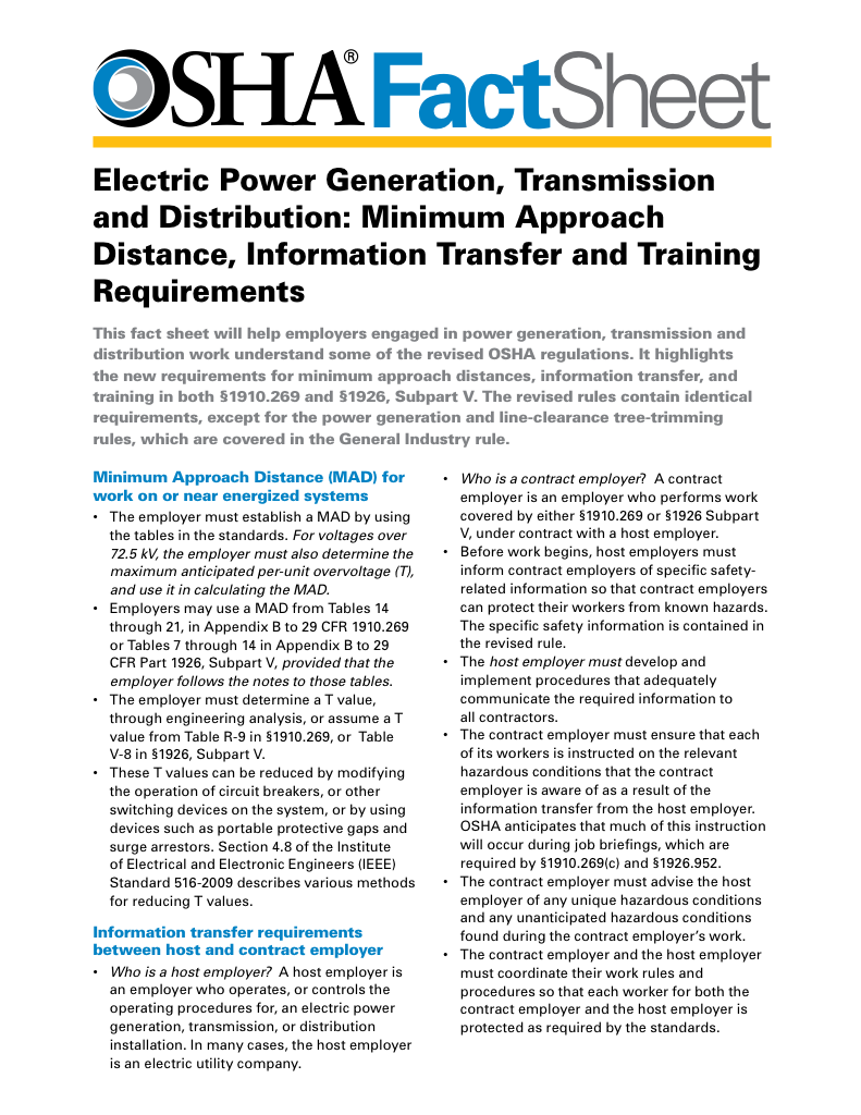
- Calculate MAD using voltage and overvoltage values
- Ensure proper communication between host and contract employers
- Meet OSHA training requirements for qualified electrical workers
A Capacitor Voltage Transformer (CVT) steps down high-voltage transmission levels for protection, metering, and control. Using a capacitive divider and electromagnetic unit, CVTs provide accurate, safe monitoring in power systems and substations.
What is a Capacitor Voltage Transformer?
A Capacitor Voltage Transformer (CVT) is a high-voltage device that utilizes a capacitor divider and electromagnetic converter to safely scale down transmission voltages for metering, protection, and power line communication.
✅ Provides accurate scaling of transmission voltages
✅ Ensures safe metering and relay protection
✅ Enables power line carrier communication
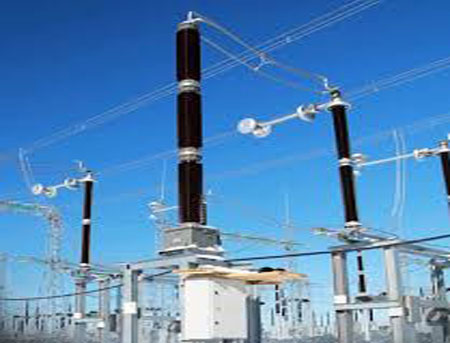
A Capacitor Voltage Transformer (CVT) is a type of voltage transformer used in high-voltage (HV) substations to step down transmission line voltages for metering and protection purposes. It utilizes a capacitive voltage divider in conjunction with an electromagnetic voltage converter to provide a scaled-down replica of the HV signal, making it suitable for use in relay and measurement equipment. A CVT is part of the broader family of electrical transformers, which are crucial for voltage (V) regulation, metering, and protection in power systems. For details on how CVTs are used in substations, see our Capacitor Voltage Transformer in Substation.
Electrical Transformer Maintenance Training
Substation Maintenance Training
Request a Free Training Quotation
This essential device steps down high transmission voltages for metering and protection and is pivotal in providing accurate measurements and safe system operations. CVTS are primarily used to step down extra-high electrical potential levels to measurable values, enabling the safe operation of measuring instruments and protective relays. Their unique construction and operational advantages make them indispensable in power line management, ensuring both precision and efficiency in measurement and communication. Understanding CVTs is vital for electricians aiming to optimize energy management and prevent costly downtime in industrial operations. For a comprehensive understanding of electrical protection mechanisms, including surge protection, explore our guide on Short Circuit Protection.
Electricity Today T&D Magazine Subscribe for FREE

- Timely insights from industry experts
- Practical solutions T&D engineers
- Free access to every issue
Differences from Traditional Voltage Transformers
Unlike conventional electromagnetic transformers, which rely solely on induction through a magnetic core, CVTs integrate capacitors to form the primary voltage divider. This arrangement reduces insulation demands and overall size, making CVTs especially cost-effective in extra-HV applications. While CVTs are designed for extra-HV transmission, a current transformer serves the complementary role of stepping down current for measurement and relay protection.
The Capacitor Voltage Divider
At the heart of a CVT lies the capacitor divider, a critical mechanism that divides the high input V into smaller, more manageable segments. This step is crucial in HV applications, where safety and accuracy are paramount. The capacitor divider operates in tandem with an instrument V converter to deliver the desired secondary electrical potential. This output is essential for feeding potential V converters, measuring instruments, and protective relays, ensuring reliable system monitoring and protection. The ability of CVTs to handle a wide range of electrical potentials makes them versatile and widely adopted across various industrial settings. Delve into the components and functionalities of electrical systems by reading about What is Switchgear?, which plays a crucial role in managing and protecting electrical circuits.
CVT Overview
| Feature / Aspect | Description | Importance in Power Systems |
|---|---|---|
| Core Function | Steps down extra-high transmission Vs using a capacitor divider and electromagnetic unit | Provides safe, measurable outputs for metering, relays, and monitoring equipment |
| Key Components | Capacitor divider, electromagnetic V converter, tuning reactor, coupling capacitors | Each part contributes to accurate scaling, insulation reduction, and communication capability |
| Difference from VT | Uses capacitors as a primary divider rather than only electromagnetic induction | Reduces insulation costs and size, adds PLC functionality |
| Working Principle | Capacitors split HV → intermediate converter isolates and steps down to safe levels | Ensures accuracy, stability, and safety in metering and protection |
| Power Line Communication Role | Couple high-frequency signals onto transmission lines | Enables data transfer across the grid without separate communication networks |
| Advantages | Compact design, reduced insulation needs, cost-effective at EHV, adaptable to multiple applications | Makes CVTs essential for modern substations and long-distance transmission systems |
| Applications | HV substations, transmission line monitoring, PLC systems | Integral to reliable and efficient energy management |
The Working Principle of CVTs
The working principle of a CVT combines capacitive division with electromagnetic isolation. HV input is split by a series of capacitors, producing a reduced intermediate V. This is passed to the electromagnetic converter, which isolates and steps it further down to standardized levels for safe use in metering and relay protection. Stability and accuracy of the secondary output are critical, and tuning reactors ensures that these are maintained under diverse operating conditions. Compared to a potential transformer, which is also used for V scaling, a capacitor voltage transformer offers additional benefits such as power line carrier communication capability.
Within this process, components such as capacitor C1 and the series capacitor stack are engineered for specific V ratings. Their performance guarantees proportional and reliable outputs even under high electrical stress. This precision is what makes CVTs so important in monitoring and protection. The testing of CVTs often follows similar practices outlined in transformer testing, ensuring accuracy, insulation reliability, and safe operation under live system conditions.
Role in Power Line Communication
In addition to electrical potential measurement, CVTs play a pivotal role in power line communication. By integrating coupling capacitors, CVTs enable the superimposition of high-frequency communication signals on the existing power line infrastructure. This capability facilitates efficient communication and control across extensive power grids, reducing the need for separate communication networks. This dual functionality of transformation and communication underlines the versatility of CVTs, making them a preferred choice in modern power systems. In industrial and utility systems, CVTs work in conjunction with instrument transformers, which provide accurate electrical quantities to metering devices and protection relays.
Advantages in High-Voltage Applications
The advantages of CVTs extend beyond their cost-effectiveness and operational efficiency. Their compact design and reduced insulation requirements make them ideal for EHV applications, where space and safety considerations are critical. Moreover, CVTs’ ability to handle a wide range of electrical potential ensures adaptability to various network configurations, further solidifying their role as a cornerstone in power system infrastructure.
Frequently Asked Questions
What is the function of a CVT?
A CVT is used in HV power systems to step down high electrical potential to lower, measurable levels for metering, protection, and control purposes. It also isolates the measurement systems from high voltage and can serve as a coupling device for power-line carrier communication (PLC), enabling data transfer over transmission lines. Understand the importance of grounding in electrical systems Grounding and Bonding, which is essential for the safe operation of surge protection devices.
Test Your Knowledge About Electrical Transformers!
Think you know Electrical Transformers? Take our quick, interactive quiz and test your knowledge in minutes.
- Instantly see your results and score
- Identify strengths and areas for improvement
- Challenge yourself on real-world electrical topics
What is the difference between a voltage transformer and a capacitive voltage transformer?
A conventional VT relies on electromagnetic induction with windings on a magnetic core. A CVT uses a capacitor divider to reduce transmission voltage before feeding it into an electromagnetic unit. This makes CVTs ideal for V above 132 kV, where cost, insulation, and PLC capability are critical. Understanding the construction and operation of CVTs is helpful when studying transformer types, as each design is tailored for specific applications, such as distribution, isolation, or HV scaling.
What is the working principle of CVT?
The CVT principle combines capacitive division with electromagnetic conversion. The capacitors reduce the line voltage, which is then stepped down further and isolated by the converter. A tuning reactor ensures accuracy by balancing reactive effects. For engineers working with HV networks, CVTs should be compared to larger electrical power transformers, which handle bulk energy transfer, whereas CVTs focus on precision measurement and protection.
Can a capacitor be used as a voltage converter?
On its own, a capacitor cannot act as a transformer. In a CVT, however, capacitors divide the high input potential before an electromagnetic converter further processes it, thereby blending the functions of both a capacitor and a transformer.
A capacitive voltage transformer is thus more than just a measuring device: it is a carefully engineered system that balances physics, design, and practical advantages. Its combination of cost savings, precision, and communication capabilities ensures its continued role in advancing reliable and efficient power systems. For a related discussion, see Surge Protection.
Related Articles


