Electrical Grounding Explained
By Pablo Diaz, P.Eng.
By Pablo Diaz, P.Eng.
Our customized live online or in‑person group training can be delivered to your staff at your location.

Electrical grounding protects people and equipment by defining how energy can flow when conditions are no longer normal. It establishes a stable electrical reference that keeps voltages predictable and protective devices coordinated.
Electrical grounding exists for a reason that is often underestimated. It gives an electrical system a fixed point of reference, so abnormal energy has a predictable place to go. Without that reference, voltage becomes unstable, insulation stress increases, and faults behave unpredictably. Before examining grounding methods and system requirements, it helps to review the basic principles introduced in our conceptual overview: understanding electrical grounding.
Stay informed with our FREE Power Quality Newsletter — get the latest news, breakthrough technologies, and expert insights, delivered straight to your inbox.
When insulation fails, conductors loosen, or external energy enters a system, grounding limits how far that energy can rise above surrounding surfaces. It does not eliminate faults. It shapes how the system responds to them.
This is why grounding is not optional in modern power systems. It is foundational. For the regulatory requirements governing the installation of grounding conductors, bonding paths, and electrodes, see our electrical grounding code reference.
Voltage has meaning only when measured against a reference. Grounding establishes that reference. It defines what “zero” means for the system, allowing all other voltages to be understood, controlled, and limited.
Once that reference exists, bonding keeps conductive surfaces at the same potential. Together, grounding and bonding prevent dangerous differences from appearing between equipment frames, enclosures, and nearby structures. Their relationship is explained more fully in our overview of grounding and bonding.
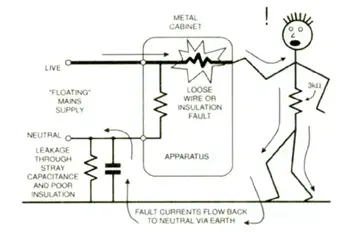
Most electrical injuries occur when a person becomes the unintended path between two different potentials. Grounding reduces that risk by keeping exposed metal parts at a common reference point and guiding fault energy away from people.
This does not rely solely on soil. It relies on electrical continuity. A well-grounded system behaves predictably during abnormal conditions. A poorly grounded one does not.
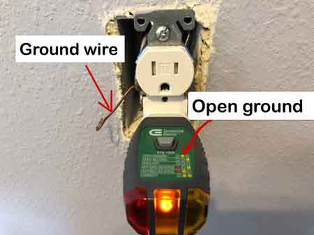
In most buildings, circuit breakers rely on a continuous ground connection to operate correctly when a short circuit or ground fault occurs. A copper wire or ground wire links equipment frames to a ground rod, metal water pipe, or other approved grounding point so fault energy has a safe return path. Without that path, the risk of electrical shock rises sharply because exposed surfaces can remain energized even after protection devices trip.
Connection integrity depends on hardware quality as much as system design, which is why the role of an electrical ground clamp is critical to maintaining long-term grounding continuity.
Grounding also protects equipment. Limiting voltage rise during faults reduces stress on insulation, switchgear, transformers, and electronic components. Over time, this improves reliability, not because faults disappear, but because their impact is controlled.
Surge energy from lightning, switching events, and static buildup is also moderated through grounding. The system remains closer to its intended operating range, avoiding damaging extremes.
Grounding is not an isolated feature. It works as part of a coordinated structure that includes conductors, bonding paths, electrodes, and protective devices. That structure is described at an architectural level in our grounding system overview.
The conductor that links the system to its earth reference plays a specific role within that structure. Its purpose and limitations are explained on the grounding electrode conductor page.
Grounding is not left to interpretation. CSA, NEC, and IEEE standards exist to ensure systems behave consistently during faults. These standards do not exist to complicate installations. They exist to prevent unpredictable electrical behavior.
For formal rule interpretation, conductor relationships, and bonding requirements, see our electrical grounding code reference.
Grounding is not simply driving a rod into the soil.
It is not a substitute for bonding.
It is not a guarantee that faults will disappear.
Grounding is a control system. It manages voltage behavior so faults remain survivable instead of destructive.
As electrical systems become more complex, grounding becomes more important, not less. Sensitive electronics, power conversion equipment, and interconnected networks all depend on stable reference and predictable fault behavior.
Download our FREE Electrical Training Catalog and explore a full range of expert-led electrical training courses.

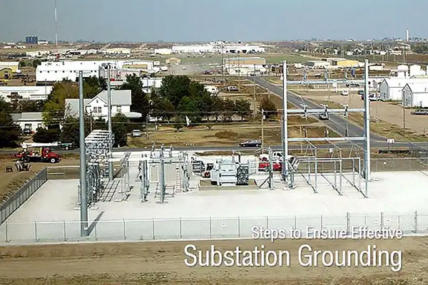
Grounding provides that predictability. Pathways must be continuous, secure, and sized appropriately based on system amperage and conductor length. Learn how a ground grid can protect substations and industrial sites by dispersing high fault current through multiple paths.
In residential systems, grounding protects occupants from energized enclosures.
In commercial buildings, it protects sensitive electronics.
In industrial facilities, it protects both personnel and production.
In utility systems, it protects networks that span miles of infrastructure.
The application changes. The purpose does not.
Specialized applications, like grounding a generator, require unique configurations to manage transient loads and maintain continuity.
Understanding electrical grounding is not about memorizing tables or conductor sizes. It is about recognizing how reference, bonding, and continuity work together to control energy when conditions are no longer normal.
When grounding is understood this way, it stops being a checklist item and becomes part of system design thinking.
Advantages To Instructor-Led Training – Instructor-Led Course, Customized Training, Multiple Locations, Economical, CEU Credits, Course Discounts.
Request For QuotationWhether you would prefer Live Online or In-Person instruction, our electrical training courses can be tailored to meet your company's specific requirements and delivered to your employees in one location or at various locations.