Understanding Electrical Grounding
By Pablo Diaz, P.Eng, Grounding Systems Technologies (GST)
By Pablo Diaz, P.Eng, Grounding Systems Technologies (GST)
Our customized live online or in‑person group training can be delivered to your staff at your location.

Understanding electrical grounding explains how earth reference, bonding, and equipotential design work together to control fault behavior, reduce shock risk, limit voltage stress, and improve system reliability.
This article focuses on common grounding misconceptions and conceptual misunderstandings rather than serving as a general grounding definition.
Electrical grounding is often discussed as if it were a single action, yet in practice, it is a relationship between reference, bonding, and fault control. Confusion usually begins when anything touching earth is assumed to be “grounded,” even though effective grounding depends far more on power continuity than on soil contact alone. For a precise terminology baseline, see our overview of how grounding controls fault voltage and current paths.
In an operating power system, grounding establishes the electrical zero reference. When a system is described as 120 volts, that value exists only in relation to this reference point. Without a common reference, voltage has no practical meaning. Equipment enclosures, raceways, and frames are therefore tied together so they remain at the same potential, reducing the chance that a person can become the lowest-impedance path between two surfaces.
In a typical electrical circuit, copper wires carry current through the circuit while neutral wires return it to the source, and grounding wires stand by to protect against electrical faults. When a ground fault occurs, a properly grounded system connects exposed metal parts back to the source, so fault energy follows a controlled path rather than passing through people or structures. This coordinated design enables modern systems to tolerate electrical faults without turning minor failures into serious hazards.
Think you know Power Quality? Take our quick, interactive quiz and test your knowledge in minutes.
Accident investigations consistently show that relying on earth itself as a safety return path creates risk rather than protection. Individual ground rods at separate pieces of equipment do not guarantee low-impedance continuity back to protective devices. Instead, they introduce unpredictable resistance that can leave enclosures energized during faults.
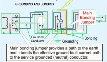
This is why bonding conductors, not soil, form the true safety pathway. A continuous, low-impedance bonding network ensures that fault current returns to the source in a controlled manner, allowing overcurrent devices to operate correctly. The practical relationship between these elements is explained further in our overview of how bonding maintains continuity between grounded components.
Once equipment frames are bonded together, the grounding system establishes its reference to earth. This does not make the earth a fault-clearing conductor. It limits voltage rise, reduces insulation stress, and stabilizes the system during abnormal conditions.
The grounding electrode and its connection to the system serve as this reference. Their role is not to carry operating fault current, but to control the voltage potential between the system and its surroundings. That distinction is explored in more detail on the conductor that connects the system to earth page.
A properly coordinated grounding arrangement also reduces the impact of static charge accumulation, lightning-induced voltages, and switching transients. Over time, this improves equipment reliability, not because faults disappear, but because the system is better prepared to tolerate them.
Grounding does not stand alone. It works as part of a larger structure that includes conductors, electrodes, bonding paths, and protective devices. That architecture is described at a system level in our overall grounding network that stabilizes system voltage overview, which shows how these pieces are arranged in practice.
Regulatory guidance from CSA, NEC, and IEEE helps standardize these relationships so that installations behave predictably during faults. If you want to see how those rules are applied in practice, our electrical grounding code reference provides the formal framework.
Understanding electrical grounding is not about memorizing conductor sizes or electrode types. It is about recognizing how reference, bonding, and continuity work together to protect people and equipment. Grounding is not a single conductor or a single connection. It is a coordinated behavior of the entire system.
When that behavior is well understood, grounding stops being a compliance exercise and becomes a reliability strategy.
Visit Our Electrical Grounding and Bonding Course
Download our FREE Electrical Training Catalog and explore a full range of expert-led electrical training courses.

Explore 50+ live, expert-led electrical training courses –