What is Power Factor? Understanding Electrical Efficiency
By R.W. Hurst, Editor

Power factor is the ratio of real power to apparent power in an electrical system. It measures how efficiently electrical energy is converted into useful work. A high power factor means less energy loss and better system performance.
What is Power Factor?
It is defined as the ratio of real power (kW), which performs useful work, to apparent power (kVA), which is the total power supplied to the system.
✅ Indicates how efficiently electrical power is used
✅ Reduces energy losses and utility costs
✅ Improves system capacity and voltage regulation
A poor power factor means that some of the supplied power is wasted as reactive power — energy that circulates in the system but does not perform useful work.
Power Quality Analysis Training
Request a Free Power Quality Training Quotation
Inductive loads, such as motors and variable speed drives, are a common cause of poor power factor. This inefficiency can lead to higher electric bills, particularly for industrial customers, because utilities often base demand charges on kVA rather than just on kW. To correct a poor power factor, capacitor banks are often installed to offset the inductive reactive power, reducing wasted energy and improving system efficiency.
A poor power factor can lead to higher electricity bills, especially for industrial customers who face demand charges based on kVA. Utilities must supply both the real and reactive components of power, which you can learn more about in our Apparent Power Formula: Definition, Calculation, and Examples guide. To correct power factor issues, capacitor banks are often installed to offset inductive effects and bring the system closer to unity power factor.
Understanding Power Factor in Electrical Systems
Power factor (PF) is not just about efficiency — it also reflects the relationship between voltage and current in an electrical circuit. It measures how closely the voltage waveform and current waveform are aligned, or "in phase," with each other.
-
Leading Power Factor: Occurs when the current waveform leads the voltage waveform. Some lighting systems, like compact fluorescent lamps (CFLs), can produce a leading power factor.
-
Lagging Power Factor: Occurs when the current waveform lags behind the voltage waveform. This is typical in systems with motors and transformers. See our article on Lagging Power Factor and How to Correct It for a detailed discussion.
-
Non-Linear Loads: Loads that distort the current waveform from its original sine wave shape, often due to switching operations within devices. Examples include electric ballasts and switch-mode power supplies used in modern electronics. Their effect on system stability is discussed in our Power Quality and Harmonics Explained guide.
-
Mixed Loads: Most real-world systems have a mix of linear and non-linear loads, which can partially cancel out some harmonic distortions.
Real, Reactive, and Apparent Power
To fully understand power factor, it helps to grasp the three types of electrical power:
-
Real (or Active) Power: The power that performs actual work in the system, expressed in Watts (W).
-
Reactive (or Non-Active) Power: The power stored and released by the system’s inductive or capacitive elements, expressed in Volt-Amperes Reactive (VARs). Explore how it’s calculated in our article on Reactive Power Formula in AC Circuits.
-
Apparent Power: The combined effect of real and reactive power, expressed in Volt-Amperes (VA). Utilities must deliver apparent power to serve all the loads connected to their networks.
The relationship between these three can be visualized as a right triangle, with real power as the base, reactive power as the vertical side, and apparent power as the hypotenuse. If you want to calculate power factor quickly, check out our simple How to Calculate Power Factor guide.
A Simple Analogy: The Horse and the Railroad Car
Imagine a horse pulling a railroad car along uneven tracks. Because the tracks are not perfectly straight, the horse pulls at an angle. The real power is the effort that moves the car forward. The apparent power is the total effort the horse expends. The sideways pull of the horse — effort that does not move the car forward — represents the reactive power.
The angle of the horse’s pull is similar to the phase angle between current and voltage in an electrical system. When the horse pulls closer to straight ahead, less effort is wasted, and the real power approaches the apparent power. In electrical terms, this means the power factor approaches 1.0 — the ideal scenario where almost no energy is wasted. For more real-world examples, we provide further explanations in Power Factor Leading vs. Lagging
The formula for calculating power factor is:
PF = Real Power ÷ Apparent Power
If your facility has poor power factor, adding a Power Factor Correction Capacitor can make a significant difference.
Causes of Low Power Factor
Low PF is caused by inductive loads (such as transformers, electric motors, and high-intensity discharge lighting), which are a major portion of the power consumed in industrial complexes. Unlike resistive loads that create heat by consuming kilowatts, inductive loads require the current to create a magnetic field, and the magnetic field produces the desired work. The total or apparent power required by an inductive device is a composite of the following:
• Real power (measured in kilowatts, kW)
• Reactive power, the nonworking power caused by the magnetizing current, required to operate the device (measured in kilovolts, power kVAR)
Reactive power required by inductive loads increases the amount of apparent power (measured in kilovolts-amps, kVA) in your distribution system. The increase in reactive and apparent power causes the PF to decrease.
Simple How-to: Correcting Power Factor
Correcting a low power factor is typically straightforward and can bring significant benefits to a facility’s energy performance. Here are some common methods:
-
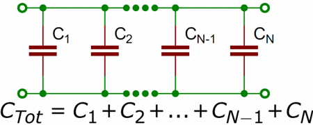
Install Capacitor Banks: Capacitors supply leading reactive power, which offsets the lagging reactive power caused by inductive loads such as motors.
-
Use Synchronous Condensers: These specialized rotating machines can dynamically correct power factor in larger industrial settings.
-
Upgrade Motor Systems: High-efficiency motors and variable frequency drives (VFDs) can reduce reactive power consumption.
-
Perform Regular System Audits: Periodic testing and monitoring can identify changes in power factor over time, allowing for proactive corrections.
Implementing power factor correction measures not only improves energy efficiency but also reduces system losses, stabilizes voltage levels, and extends the lifespan of electrical equipment.
Industries Where Power Factor Correction Matters
Industries that operate heavy machinery, large motors, or lighting banks often struggle with low PF. Facilities interested in monitoring their system health can benefit from tools like a Power Quality Analyzer Explained. Proper correction reduces wasted energy, prevents overheating, and extends the equipment's lifespan.
Power factor management is especially important for utilities and high-demand commercial sites, where poor PF can impact both Quality of Electricity and system reliability.
Some key sectors where maintaining a high power factor is vital include:
-
Manufacturing Plants: Motors, compressors, and welding equipment can cause significant reactive power demands.
-
Data Centers: The large number of servers and cooling systems contributes to power inefficiencies.
-
Hospitals: Medical imaging machines, HVAC systems, and other critical equipment generate substantial electrical loads.
-
Commercial Buildings: Lighting systems, elevators, and HVAC units can result in a low power factor without proper correction.
-
Water Treatment Facilities: Pumps and filtration systems involve extensive motor usage, requiring careful management of power quality.
Improving the power factor in these industries not only reduces utility penalties but also enhances the reliability of critical systems.
Frequently Asked Questions
What is a good power factor, and why does it matter?
A power factor (PF) of 1.0 (or 100%) is ideal, indicating that all the power supplied is effectively used for productive work. Utilities typically consider a PF above 0.9 (90%) as acceptable. Maintaining a high PF reduces energy losses, improves voltage stability, and can lower electricity costs by minimizing demand charges.
How does low power factor increase my electricity bill?
When your PF drops below a certain threshold (often 90%), utilities may impose surcharges to compensate for the inefficiencies introduced by reactive power. For instance, BC Hydro applies increasing penalties as PF decreases, with surcharges reaching up to 80% for PFs below 50% . Improving your PF can thus lead to significant cost savings.
What causes a low power factor in electrical systems?
Common causes include:
-
Inductive loads: Equipment like motors and transformers consume reactive power.
-
Underloaded motors: Operating motors below their rated capacity.
-
Non-linear loads: Devices like variable frequency drives and fluorescent lighting can distort current waveforms, leading to a lower PF.
How can I improve my facility's power factor?
Improvement strategies encompass:
-
Installing capacitor banks: These provide reactive power locally, reducing the burden on the supply.
-
Using synchronous condensers: Particularly in large industrial settings, they help adjust PF dynamically.
-
Upgrading equipment: Replacing outdated or inefficient machinery with energy-efficient models.
-
Regular maintenance: Ensuring equipment operates at optimal conditions to prevent PF degradation.
Does power factor correction benefit the environment?
Yes. Enhancing PF reduces the total current drawn from the grid, leading to:
-
Lower energy losses: Less heat generation in conductors.
-
Improved system capacity: Allowing more users to be served without infrastructure upgrades.
-
Reduced greenhouse gas emissions: As overall energy generation needs decrease.
Related Articles


