Power Factor Correction Capacitor
By R.W. Hurst, Editor
By R.W. Hurst, Editor
Our customized live online or in‑person group training can be delivered to your staff at your location.

Power factor correction capacitor selection defines kVAR compensation, voltage class tolerance, and harmonic interaction limits in three phase systems. Incorrect detuning, improper kvar step configuration, or inadequate dielectric margin can amplify distortion, elevate thermal stress, and create compliance exposure under industrial load variability.
Reactive power management is not a billing optimization exercise. In industrial facilities with concentrated motor loads and variable drives, a capacitor bank modifies system impedance and short circuit characteristics. That impedance shift affects harmonic amplification, protection coordination, and transformer heating margins across the distribution network.
When capacitors are installed without structured harmonic assessment, resonance conditions can elevate total harmonic distortion beyond acceptable thresholds. The consequence is not simply reduced equipment life. It can alter fault current distribution, increase reactive current circulation, and trigger misoperation of protection devices in three phase systems operating near capacity.
Capacitor deployment must be evaluated within the broader context of power quality, where voltage distortion limits, harmonic thresholds, and compliance exposure define acceptable operating boundaries in industrial power systems.
Power factor correction capacitor sizing begins with reactive demand, but it cannot end there. The capacitor bank kVAR rating must align with the system’s apparent load profile and expected kvar compensation range under peak and minimum operating conditions. Capacitor bank configuration must also account for kvar rating tolerance to prevent reactive output from exceeding acceptable limits during light load or harmonic current loading conditions. Oversizing to force unity conditions introduces leading reactive current during light load, increasing overvoltage exposure on lightly loaded feeders.

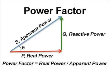
In three phase installations, the three phase kvar per phase distribution must remain balanced within the capacitor tolerance band to prevent unequal current sharing and premature element failure. A misaligned kvar rating per phase can shift stress to one portion of the bank, accelerating dielectric degradation under distortion conditions. System loading assumptions must be grounded in accurate modeling of Apparent Power rather than simplified displacement targets.
The kVAR requirement must be derived from measured operating conditions rather than static nameplate assumptions. Engineers frequently validate compensation targets through structured Power Factor Calculation, but field measurements must confirm both displacement and distortion components before finalizing kvar compensation levels.
Voltage class selection is a threshold discipline issue. A capacitor rated at 480 V nominal must tolerate sustained overvoltage, harmonic voltage rise, and switching transient stress. Rated voltage withstand must be evaluated against both steady state overvoltage and repetitive switching duty cycle stress, since insulation margin erodes under combined electrical and thermal loading. Capacitor dielectric loss increases as harmonic voltage distortion rises, and excessive loss factor accelerates internal heating beyond the capacitor bank's design thermal envelope. Thermal aging of dielectric material accelerates when harmonic current loading elevates internal temperature beyond rated limits, directly reducing expected service life under continuous industrial operation.
Because dielectric stress increases with both sustained overvoltage and distortion loading, the rated reactive current becomes the governing thermal boundary condition. An underspecified voltage class increases failure probability under harmonic stress.
A PF correction capacitor shifts the system resonance frequency. In three phase industrial networks with dominant harmonic components, the parallel resonance point can migrate toward harmonic injection frequencies described in Power Quality and Harmonics.
In high harmonic industrial networks, capacitor misapplication is not an efficiency error. It is a system impedance modification that can alter fault current distribution and protection coordination.
In installations requiring harmonic mitigation, the detuned capacitor bank must be coordinated with upstream impedance to avoid resonance near dominant harmonic orders. Reactor impedance must correspond to the total capacitor bank kVAR rating so that harmonic amplification does not exceed the rated reactive current under distortion scenarios. Improper coordination between detuned elements and upstream system inductance can alter capacitor bank configuration behavior, increasing reactive current circulation and shifting resonance toward dominant harmonic frequencies.
Cascading consequences occur when resonance increases voltage distortion, which, in turn, increases reactive current and heating within the capacitor bank. Elevated temperature increases dielectric loss, reduces insulation life, and restricts transformer capacity margin.
Under sustained harmonic current loading, rated reactive current can be exceeded even when displacement power factor appears acceptable, causing progressive dielectric stress and accelerated thermal degradation within the capacitor bank elements.
Fixed Power factor correction capacitor banks are acceptable only when the reactive demand is stable. Where load fluctuates, kvar step increments must be structured to track demand without inducing sustained leading conditions. Industrial installations commonly use 25 kVAR or 50 kVAR increments, and automated switching is typically managed through an Automatic Power Factor Controller.
When a kvar step closes onto an energized bus, switching inrush current can momentarily reach multiples of rated reactive current. Each kvar step must include an appropriate discharge resistor to ensure that residual voltage decays before reclosing; otherwise, the switching transient magnitude can exceed the dielectric withstand rating. Switching duty cycle must be evaluated against manufacturer limits, as excessive operations per hour increase mechanical wear, elevate dielectric stress, and shorten expected service life of the capacitor bank.
Stay informed with our FREE Power Quality Newsletter — get the latest news, breakthrough technologies, and expert insights, delivered straight to your inbox.
Repeated exposure to switching transient peaks must be evaluated against rated voltage withstand limits, as cumulative dielectric fatigue from high magnitude inrush current can reduce insulation margin over time.
Deployment must be validated through measurement. Post installation verification using a Power Quality Analyzer confirms voltage distortion, harmonic spectra, reactive current levels, and displacement correction under varying load conditions. Capacitor bank protection schemes must include coordinated fuse coordination and overcurrent settings to ensure that internal faults isolate rapidly without propagating disturbance across adjacent feeders.
For facilities with multiple feeders, kvar compensation per feeder must be coordinated to prevent localized overcompensation that shifts impedance unevenly across the three phase distribution network. Ongoing validation through structured Power Quality Monitoring ensures that switching events do not introduce flicker, distortion excursions, or unintended resonance.
Thermal trending of capacitor bank operating temperature and periodic verification of reactive current levels are necessary to confirm that expected service life assumptions remain valid under actual harmonic and switching duty cycle conditions.
If reliability metrics are a board level performance variable, capacitor failure is not a maintenance inconvenience. It is a governance failure with cascading operational consequences.
A power factor correction capacitor is therefore not an accessory device. It is an impedance modifying component whose capacitor bank kVAR rating, rated reactive current, dielectric loss characteristics, kvar tolerance, and switching transient behavior determine whether the three phase system remains stable under distortion and load variability.
System stability ultimately depends on aligning capacitor bank configuration, kvar rating tolerance, and rated reactive current boundaries with actual harmonic current loading and voltage stress conditions across the three phase distribution system.
Explore 50+ live, expert-led electrical training courses –