Power Factor Cos phi (cos φ) and Electrical Systems
By William Conklin, Technical Editor
By William Conklin, Technical Editor
Our customized live online or in‑person group training can be delivered to your staff at your location.

Power factor cos φ is the ratio of real power to apparent power in an AC circuit. It measures energy efficiency. A higher power factor indicates efficient energy use, while a low power factor can lead to increased utility costs and reduced system performance.
Power Quality Analysis Training
Request a Free Power Quality Training Quotation
Power factor cos φ measures the phase angle between real and apparent power in an AC circuit. A lower angle improves electrical efficiency, reduces energy waste, and helps achieve better load management and system performance across industrial and commercial operations.
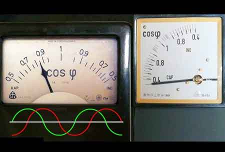
In AC electrical systems, cos φ (cosine phi) describes the phase difference between voltage and current. It is the mathematical value of the power factor (PF), representing the efficiency with which electricity is converted into useful work. In simple terms, cos φ measures how much of the electrical energy supplied to a system is being used effectively.
The formula is straightforward:
cos φ = Real Power (kW) ÷ Apparent Power (kVA)
When voltage and current are perfectly aligned, cos φ equals 1, meaning the system is fully efficient. As the phase angle increases due to inductive or capacitive loads, cos φ decreases, indicating a greater presence of reactive elements and lower efficiency.
To calculate cos φ, you need two basic measurements:
Real Power (kW): The energy used to perform actual work.
Apparent Power (kVA): The combination of real and reactive components.
Example: Suppose a motor consumes 600 kW of real energy, and the apparent energy drawn from the source is 750 kVA. The calculation would be:
cos φ = 600 ÷ 750 = 0.8
This means the system operates at 80% efficiency, and 20% of the supply is lost to reactive effects.
Stay informed with our FREE Power Quality Newsletter — get the latest news, breakthrough technologies, and expert insights, delivered straight to your inbox.
For more on how to calculate these values step-by-step, see our How to Calculate Power Factor guide.
The following equation relates these three types of energy:
(S)² = (P)² + (Q)²
From this, we can derive the formulas for active and Q:
P = S * cos φ
Q = S* sin φ
Maintaining a high cos φ is critical in industrial and commercial environments. Poor values often result in higher utility bills, increased losses, and even equipment overheating. Many utility companies impose penalties for low cos φ readings to encourage better electrical system design.
Installing correction devices, such as capacitors, can improve cos φ by reducing the phase shift between current and voltage. Learn how this works in our Power Factor Correction overview.
A low cos phi, indicative of a high proportion of Q, has several detrimental consequences:
Increased Transmission Losses: Higher Q necessitates increased current flow through transmission lines, resulting in higher energy losses due to resistance. This results in wasted energy and increased operating costs.
Elevated Grid Load: Excessive Q burdens the grid, requiring larger transformers, thicker cables, and increased generation capacity. This can strain the grid infrastructure and potentially lead to instability.
Overheating of Equipment: High reactive currents can cause overheating in electrical equipment, reducing their lifespan and increasing the risk of failure. This can disrupt operations and lead to costly repairs or replacements.
Financial Penalties: Many utility companies impose penalties on industrial consumers with low PF, as they contribute to inefficiencies in the electrical system. These penalties can significantly impact operational expenses.
Improving power factor (PF) involves reducing the quality factor (Q) and minimizing phase shift. Several techniques are employed to achieve this:
Capacitor Banks: Capacitor banks are widely used to compensate for inductive Q. By introducing capacitive reactance, they counteract the inductive reactance, effectively reducing the overall Q and improving the PF.
Static VAR Compensators (SVCs): SVCs are sophisticated devices that dynamically adjust the Q supplied to the system. They continuously monitor the PF and inject or absorb Q as needed to maintain a desired value.
Synchronous Condensers: Synchronous condensers are rotating machines that can be operated in overexcited mode to generate capacitive Q. They offer precise control over Q and can be used in high-voltage applications.
Harmonic Filters: Harmonic filters are designed to mitigate harmonic distortion in the electrical system. By suppressing harmonic currents, they improve PQ and contribute to PF correction.
cos φ = kW ÷ kVA
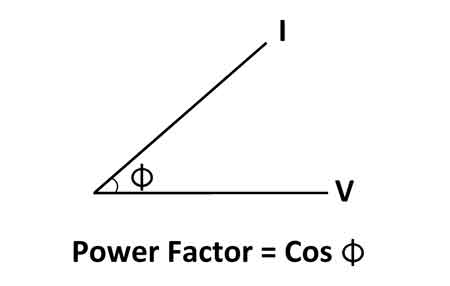
A simple triangle diagram shows the relationships:
Base = Real Power (kW)
Hypotenuse = Apparent Power (kVA)
Height = Reactive Power (kVAR)
For a full explanation of these relationships, visit What is Power Factor.
Cos phi, as a measure of PF, serves as a critical parameter in AC electrical systems. Understanding its significance and the implications of a low PF is crucial for optimizing energy efficiency, reducing costs, and ensuring the reliable operation of electrical infrastructure. By implementing appropriate power factor (PF) correction techniques, industries can enhance their operational efficiency, contribute to a more stable grid, and promote environmental sustainability.

Advantages To Instructor-Led Training – Instructor-Led Course, Customized Training, Multiple Locations, Economical, CEU Credits, Course Discounts.
Request For QuotationWhether you would prefer Live Online or In-Person instruction, our electrical training courses can be tailored to meet your company's specific requirements and delivered to your employees in one location or at various locations.