Latest Utility Transformers Articles
Feature Selection For Effective Health Index Diagnoses Of Power Transformers
Feature selection for effective health index diagnoses of power transformers drives predictive maintenance, DGA analytics, machine learning classification, and condition monitoring, improving asset management, failure risk assessment, and lifecycle reliability across utility fleets.
Feature Selection for Effective Health Index Diagnosis of Power Transformers Explained for Electrical Professionals
Feature selection for effective health index diagnoses of power transformers is a critical process in ensuring the reliability and longevity of these essential utility assets. By identifying and analyzing the most relevant parameters—such as temperature, dissolved gas analysis, insulation condition, and load variations—feature selection enhances predictive maintenance and fault detection. This data-driven…
View more
Sign Up for Electricity Forum’s Utility Transformers Newsletter
Stay informed with our FREE Utility Transformers Newsletter — get the latest news, breakthrough technologies, and expert insights, delivered straight to your inbox.
Reactors In Power System And Its Afffect On Transformer
Reactors in Power System and Its Afffect on Transformer mitigate fault current, damp inrush and transients, add series impedance, reduce harmonics, and enhance voltage regulation for grid stability and transformer protection.
Understanding Reactors in Power Systems and Their Effect on Transformers: Principles and Applications
Reactors in power systems control voltage levels, limit fault currents and improve power quality in utility transformers. These inductive components are strategically installed to manage reactive power, mitigate short-circuit currents, and reduce voltage fluctuations, ensuring the stability and efficiency of the electrical grid. Without reactors, transformers can experience excessive voltage stress, increased losses, and potential…
View more
Dissolved Gas Analysis Methods for Transformer Diagnostics
Dissolved gas analysis methods interpret transformer fault gases using structured ratio, graphical, and standards-based frameworks to classify internal electrical and thermal faults for reliable transformer condition assessment.
Dissolved gas analysis methods provide the structured logic that transforms raw gas measurements into meaningful transformer fault classifications. Without interpretation frameworks, DGA remains a list of gas concentrations rather than a diagnostic system.
These methods do not replace engineering judgment. Instead, they provide disciplined tools that allow consistent interpretation of transformer fault behavior across operating conditions, designs, and asset populations.
Why Dissolved Gas Analysis Methods Matter
Transformers generate multiple gases simultaneously during…
View more
The Role of AI and Machine Learning in Predicting Transformer Faults
AI and Machine Learning can predict transformer faults by analyzing dissolved gas data, thermal patterns, and vibration trends to identify insulation degradation, detect anomalies, and prevent costly power transformer failures before they occur.
Why AI Integration into Transformer Diagnostics Matters
Applies machine learning to transformer data for predictive fault detection.
Analyzes DGA, temperature, and vibration trends for early anomaly alerts.
Enhances reliability through automated, data-driven maintenance decisions.
Electrical Transformer Maintenance Training
Substation Maintenance Training
Request a Free Training Quotation
The Shift Toward Predictive Intelligence
Artificial intelligence (AI) and machine learning (ML) are revolutionizing transformer diagnostics by transforming…
View more
Dissolved Gas Analysis Of Transformer Oil
Dissolved Gas Analysis evaluates gases dissolved in transformer insulating oil to identify internal electrical and thermal faults early, supporting predictive maintenance decisions that protect transformer reliability and reduce unplanned outages.
Dissolved Gas Analysis (DGA) is one of the most trusted diagnostic tools for assessing the internal condition of a transformer. By measuring fault gases dissolved in insulating oil, DGA reveals developing problems inside windings, insulation, and core structures long before external symptoms appear.
For utilities and industrial operators, DGA is not simply a laboratory test. It is a decision system that guides maintenance timing, risk prioritization, and asset life management…
View more
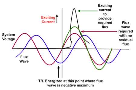
Excitation Current
Excitation current establishes transformer core flux and reflects magnetic losses, efficiency, and structural condition. Tracking its behavior helps detect core degradation, rising losses, and reliability risk long before visible failure occurs.
Excitation current is not a background electrical detail. In transformer operation, it is a diagnostic signal that reflects core magnetizing behavior, internal loss mechanisms, and early indications of structural or material change. Engineers and maintenance professionals rely on its behavior not to understand what a transformer is doing in theory, but to judge what is happening inside it in practice.
A transformer draws current even when its secondary is…
View more
Characteristics of Dielectric Fluid
Characteristics of Dielectric Fluid describe how insulating liquids withstand voltage, control heat, and age in transformers. Important properties include dielectric strength, permittivity, moisture resistance, oxidation stability, and thermal conductivity.
In practical transformer operation, the Characteristics of Dielectric Fluid determine whether insulating fluids can maintain electrical integrity, remove heat efficiently, and resist chemical degradation over long service periods. Variations in these properties directly influence insulation life, fault risk, and maintenance planning.
Dielectric liquids are selected not only because they are electrically insulating, but because they behave predictably as a dielectric material across a wide temperature range under high voltage stress.
When…
View more