Transformer Wiring Diagram Explained

Substation Maintenance Training
Our customized live online or in‑person group training can be delivered to your staff at your location.

- Live Online
- 12 hours Instructor-led
- Group Training Available
Download Our OSHA 3075 Fact Sheet – Understanding Electrical Hazards in the Workplace

- Learn the effects of electric current on the human body
- Understand OSHA safety standards and protective devices
- Discover essential lockout/tagout and grounding practices
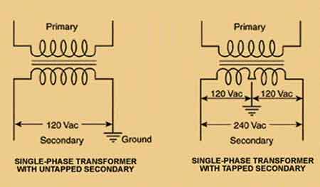
A transformer wiring diagram illustrates the correct connection of primary and secondary windings for effective voltage transformation. It ensures correct electrical connections, aids in troubleshooting, and supports safe installation of power, distribution, or control transformers.
What is a Transformer Wiring Diagram?
A transformer wiring diagram is fundamental for electrical engineering and maintenance professionals.
✅ Shows electrical connections for primary and secondary windings
✅ Helps in installing, troubleshooting, and maintaining transformers
✅ Ensures proper voltage transformation and safety compliance
This visual representation depicts how the windings are interconnected, significantly impacting their operation and performance. A thorough understanding of this diagram is crucial for several reasons: it facilitates proper installation, troubleshooting, and maintenance; it ensures safe and efficient power distribution; and it enables the selection of the most suitable transformer configuration for specific applications.
To grasp these diagrams, it's important first to understand what is a transformer, including its function of increasing or decreasing voltage. This foundational knowledge helps interpret wiring for both control transformers and measurement-class devices, such as current transformers.
The intricacies of a transformer wiring diagram reveal more than just lines and labels; they encapsulate the heart of electrical systems. A well-constructed wiring diagram not only aids in understanding transformer connections but also ensures the safety, reliability, and efficiency of power distribution systems. These diagrams provide indispensable guidance, whether dealing with single-phase transformer connections or more complex three-phase transformers.
Electrical Transformer Maintenance Training
Substation Maintenance Training
Request a Free Training Quotation
The intricacies of a transformer wiring diagram reveal more than just lines and labels; they encapsulate the heart of electrical systems. A well-constructed wiring diagram not only aids in understanding transformer connections but also ensures the safety, reliability, and efficiency of power distribution systems. These diagrams provide indispensable guidance, whether dealing with three-phase configurations or single-phase transformers.
Test Your Knowledge About Utility Transformers!
Think you know Utility Transformers? Take our quick, interactive quiz and test your knowledge in minutes.
- Instantly see your results and score
- Identify strengths and areas for improvement
- Challenge yourself on real-world electrical topics
Three-Phase Connections
Transformer connections vary widely depending on their purpose, and three-phase configurations form the backbone of modern electrical grids. Diagrams illustrating Delta-Delta (Δ-Δ), Star-Star (Y-Y), Delta-Star (Δ-Y), and Star-Delta (Y-Δ) arrangements are particularly common. For example, understanding delta-to-wye conversion is crucial when modifying system configurations to meet specific voltage requirements.
Each configuration has unique attributes that suit specific applications. For instance, the Delta-Delta connection offers robustness for high-load environments, while Delta-Star is valued for its ability to step down voltage efficiently, providing a stable secondary connection. These wiring configurations are indispensable in industrial and commercial setups, where detailed diagrams ensure proper implementation.
Open Delta (V-V) Connection
One noteworthy arrangement often encountered in diagrams is the open delta (V-V) connection. This innovative design proves invaluable when one transformer in a Delta-Delta system fails. By rearranging the wiring to form an open delta, the system can continue operating, albeit at a reduced capacity. Such versatility underscores the importance of wiring diagrams in troubleshooting and maintaining system resilience. Including precise depictions of open delta arrangements allows technicians to make informed decisions during unexpected outages.
Scott-T Transformer Connection
Another fascinating aspect of wiring is the Scott-T connection, used to convert three-phase power into two-phase power or vice versa. These diagrams are particularly relevant in niche industrial applications where legacy equipment requires two-phase input. By clearly outlining the interconnection of windings, Scott-T wiring diagrams ensure that even complex transitions between power systems are executed seamlessly. Understanding these diagrams can bridge the gap between old and new electrical infrastructures.
Wiring Color Codes and Standards
Beyond connection configurations, adherence to wiring color codes and standards is crucial for safety and compliance. Every diagram should reflect established guidelines, especially in three-phase systems. Clear identification of phases through standardized colors prevents miswiring, which could lead to hazardous situations. For example, secondary connections in single-phase units must be distinctly marked to avoid confusion during installation or maintenance. Wiring diagrams that incorporate these standards promote safer practices and easier troubleshooting.
Voltage Transformer Connections
Voltage transformer connections, often included in wiring diagrams, are essential for protective applications in power systems. These connections enable accurate measurement and relay functionality, critical for maintaining system integrity. For example, capacitor voltage transformers are used to isolate metering equipment while stepping down voltage for monitoring.
Protective relaying systems rely on precise voltage readings to identify and isolate faults, minimizing potential damage. Wiring diagrams play a pivotal role in safeguarding infrastructure and ensuring uninterrupted power delivery by detailing these connections.
The comprehensive nature of a diagram extends beyond technicalities, offering a visual guide that simplifies complex systems. A 3-phase to single-phase transformer diagram, for instance, illustrates the interaction between the primary and secondary windings, ensuring that the voltage ratios align with operational requirements. In larger systems, these diagrams facilitate the integration of multiple transformers, helping engineers visualize how components interconnect to meet demand. Diagrams transform abstract electrical concepts into actionable insights by mapping out these connections.
Wiring diagrams also highlight the evolution of electrical systems. Technological advances have introduced innovations such as automation and smart grids, requiring updated approaches to transformer wiring. Modern diagrams incorporate additional components, such as sensors and communication modules, reflecting the evolving landscape of power systems. These enhancements improve monitoring and control, making connections more efficient and adaptive to dynamic load conditions.
It is an indispensable tool in the electrical industry, bridging the gap between theory and application. These diagrams enable precise implementation and maintenance by illustrating configurations such as Delta-Delta, Scott-T, and open delta. They also reinforce the importance of standards like wiring color codes, ensuring safety and compliance. From single-phase units to advanced protective applications, wiring diagrams provide clarity and reliability, fostering a deeper understanding of electrical systems. As the industry continues to evolve, electrical transformers will remain central to the energy infrastructure, and wiring diagrams will continue to be a cornerstone of effective power distribution.
Electricity Today T&D Magazine Subscribe for FREE

- Timely insights from industry experts
- Practical solutions T&D engineers
- Free access to every issue


