High Voltage Transformers
Substation Maintenance Training
Our customized live online or in‑person group training can be delivered to your staff at your location.
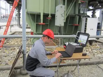
- Live Online
- 12 hours Instructor-led
- Group Training Available
Download Our OSHA 4475 Fact Sheet – Being Aware of Arc Flash Hazards
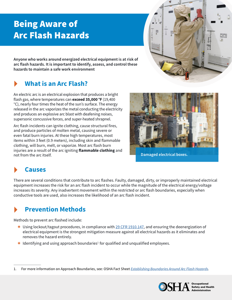
- Identify root causes of arc flash incidents and contributing conditions
- Apply prevention strategies including LOTO, PPE, and testing protocols
- Understand OSHA requirements for training and equipment maintenance
High voltage transformers step up or step down electrical energy in transmission and distribution systems. These critical devices ensure efficient power flow, voltage regulation, and grid reliability across utility, industrial, and renewable energy applications.
What are High Voltage Transformers?
High voltage transformers are electrical devices that transfer electrical energy between two or more circuits through electromagnetic induction. They:
✅ Convert electricity between different voltage levels for safe transmission and distribution.
✅ Are essential in power grids, substations, and renewable energy systems to maintain efficiency and stability.
✅ Support industrial, utility, and commercial applications requiring reliable voltage control.
Electrical Transformer Maintenance Training
Substation Maintenance Training
Request a Free Training Quotation
They operate by stepping up (increasing) or stepping down (decreasing) the voltage (V) levels in power systems. High voltage transformers are typically used in transmission and distribution networks to move electricity over long distances efficiently. They work by using coils of wire (primary and secondary windings) wrapped around a magnetic core. When V is applied to the primary winding, a magnetic field is created, inducing a V in the secondary winding, which transfers power at a higher or lower V depending on the transformer design. High voltage transformers are closely tied to utility transformers, which play a vital role in large-scale power distribution and grid reliability.
High voltage transformers play a crucial role in distribution systems by stepping up or stepping down voltages to ensure efficient power transmission and distribution. These devices are designed to handle a wide V range, making them versatile for various applications. There are different types used in distribution systems, including step-up ones, which increase V for long-distance transmission, and step-down ones, which reduce V for safe distribution to homes and businesses. Selecting the right type of transformer is essential for maintaining grid stability and efficiency. Understanding the construction of a transformer offers insight into how its components, including cores, windings, and insulation, contribute to its performance and safety.
Sign Up for Electricity Forum’s Utility Transformers Newsletter
Stay informed with our FREE Utility Transformers Newsletter — get the latest news, breakthrough technologies, and expert insights, delivered straight to your inbox.
Frequently Asked Questions
What are the different types of high voltage transformers?
There are several types used in high-voltage applications, including:
-
Power Transformers: These are used in transmission networks to transfer electrical energy at high-voltage levels, typically for long-distance transmission.
-
Distribution Transformers: These are designed for lower V levels and are used to supply power directly to homes and businesses in distribution systems. A distribution transformer steps down the voltage for safe delivery to homes and businesses, making it one of the most common types of transformers.
-
Autotransformers: These transformers share primary and secondary windings and are used when a small vV change is needed.
-
Instrument Transformers: These are used for measurement and protection in high voltage circuits, including current and potential transformers.
Each type is designed for specific applications in the power system, with different V ranges and configurations.
They can be configured as either a single-phase primary configuration or a three-phase configuration. The size and cost of a transformer increase when you move down the listing of primary high-power V windings. Single-phase primary configurations include single, dual, quad (2+2), 5-lead, and ladder. A 5-Lead primary requires more copper than a Quad (2+2) primary. A Ladder is the least economical primary configuration. Three-phase high-voltage transformers are typically connected in either a delta or wye configuration. A wye-delta transformer has its primary winding connected in a wye and its secondary winding connected in a delta. A delta-wye transformer has its primary winding connected in a delta and its secondary winding connected in a wye. For engineers and technicians, knowing how transformers work is fundamental to applying them effectively in power systems.
Three-phase high-voltage power configuration choices include delta-delta, delta-wye (Y), wye (Y)–wye (Y), wye (Y)–delta, wye (Y)–single-phase, delta–single–phase, and international. Primary frequencies of the incoming V signal to primaries available for high-voltage transformers include 50 Hz, 60 Hz, and 400 Hz. 50 Hz is the standard frequency for European power. 60 Hz is a common frequency in North American power systems. 400 Hz is most widely used in aerospace applications. The maximum primary input V rating is another important parameter to consider. A transformer should be provided with more than one primary winding if it is to be used for several nominal voltages to avoid a short circuit.
What is the voltage range of high voltage transformers?
The V range typically starts at 35 kV (kilovolts) and can extend up to several hundred kV. For example, devices used in transmission networks typically operate at voltages ranging from 110 kV to 765 kV. Distribution systems typically use ones that step down voltage to lower levels, ranging from 35 kV down to 400 V for use in residential and commercial applications.
Other important specifications to consider when searching for high-voltage transformers include the maximum secondary voltage rating, maximum secondary current rating, maximum power rating, and output type. A transformer may provide more than one secondary V value. The Rated Power of the transformer is the sum of the VA (Volts x Amps) for all of the secondary windings. Output choices include AC or DC. For Alternating Current waveform output, the V values are typically given in RMS (Root Mean Square) values. Consult manufacturers of core transformers for waveform options. For a direct current secondary voltage output power supply, consult the manufacturer for the type of rectification. In substations, a dedicated electrical substation transformer ensures V levels are adapted for both transmission and distribution needs.
Test Your Knowledge About Utility Transformers!
Think you know Utility Transformers? Take our quick, interactive quiz and test your knowledge in minutes.
- Instantly see your results and score
- Identify strengths and areas for improvement
- Challenge yourself on real-world electrical topics
What are the key components of high voltage transformers?
The key components of a high voltage transformer include:
-
Windings: The primary and secondary coils that carry the electrical current and induce V through electromagnetic induction.
-
Core: A magnetic core made of iron or steel that provides a low-resistance path for the magnetic field and enhances efficiency.
-
Insulation: Materials that insulate the windings and core from each other to prevent short circuits and ensure safe operation.
-
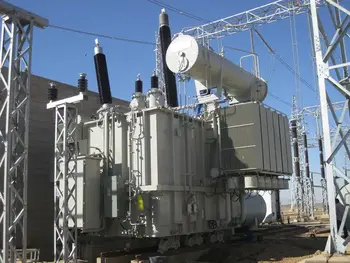
Bushings: Insulated devices that allow high-voltage conductors to pass through the transformer casing safely.
-
Cooling System: High voltage transformers require cooling mechanisms (oil or air) to dissipate heat generated during operation.
The performance of high voltage transformers depends on proper insulation and oil systems, as discussed in transformer components.
Related Articles


