Arc Flash Boundary Table by Incident Energy Explained
An arc flash boundary table by incident energy is a critical tool to determine the safe working distance from electrical equipment where an arc flash hazard exists.
Incident energy determination is based on the level of incident energy, measured in calories per square centimeter (cal/cm²), which indicates the severity of potential heat exposure during an arc flash event. Using this calculation, electricians and safety professionals can establish the proper boundary to protect workers from the dangers of arc flashes, ensuring that they are positioned far away to avoid serious burns or injuries. This plays a vital role in selecting the appropriate personal protective equipment (PPE) and following proper safety protocols in compliance with electrical safety standards.
Request a Free Training Quotation
How is an arc flash boundary table based on incident energy?
An arc flash boundary table defines the minimum safe distance from an electrical fault source where the incident energy falls to 1.2 cal/cm²—the threshold at which second-degree burns can occur. Beyond this point, the use of arc-rated personal protective equipment (PPE) is mandatory to ensure worker safety.
This boundary is influenced by multiple factors, including system voltage, available fault current, and the clearing time of overcurrent protection devices. Accurate determination of this distance often requires an incident energy analysis, as outlined in IEEE 1584. This standard offers detailed formulas and modeling guidance to calculate arc flash boundaries based on real-world electrical system configurations. Additionally, NFPA 70E Section 130.5 provides further direction for identifying safe working distances for various tasks and equipment setups.
| Incident Energy (cal/cm²) | Minimum Arc Flash Boundary (inches) | Minimum Arc Flash Boundary (mm) | PPE Category |
|---|---|---|---|
| 1.2 | 18 | 457 | Minimum PPE Required |
| 4.0 | 24 | 610 | Category 1–2 (8 cal/cm²) |
| 8.0 | 36 | 914 | Category 3 (25 cal/cm²) |
| 25 | 60 | 1524 | Category 4 (40 cal/cm²) |
| 40 | 72 | 1829 | Custom PPE Required |
Arc Flash Boundary Table By Incident Energy
Notes:
-
1.2 cal/cm² is the threshold for second-degree burns and establishes the arc flash protection boundary.
-
Actual boundaries depend on system-specific variables including voltage, fault current, clearing time, and working distance.
-
Always refer to an incident energy analysis and IEEE 1584 calculations for precise arc flash boundary determinations.
How Does Energy Affect the Electrical Boundary?
The amount of energy released during a fault directly impacts the size of the boundary. Higher energy levels result in a greater distance that must be maintained for safety, as the risk of burns increases with energy intensity.
Energy is determined by several factors, such as the system's design, including arcing faults, and the fault-clearing time. Another important variable is the distance between the worker and the equipment, known as the working distance. The closer the worker is to the fault, the higher the energy exposure; therefore, the boundary must be adjusted accordingly.
Energy is typically calculated using the incident energy calculation method or the flash PPE categories method, which assigns protective clothing based on potential exposure levels. The arc flash incident energy table 130.7(c)(15), helps guide workers in choosing the right protective equipment based on energy levels and tasks.
What Are the Typical Working Distances for Different Voltages?
The working distance is critical in determining how far away a worker should stay from electrical equipment. For systems operating at different voltage levels, typical distances vary:
- For low-voltage equipment, such as 480V panels, an 18-inch working distance is common.
- For medium-voltage equipment, such as switchgear, distances often range from 24 to 36 inches.
- For high-voltage systems, working distances can extend beyond 36 inches, depending on the equipment and risk assessment.
Energy exposure decreases as the worker and the equipment distance increases, leading to smaller required boundaries.
How Do Electrode Configurations Affect the Electrical Boundary?
Electrode configurations influence the behaviour of electrical faults and, therefore, the size of the boundary. The way conductors are arranged inside an enclosure impacts how energy is dispersed. Some typical configurations defined in IEEE 1584 include:
- Vertical conductors in a box are the most common setup for electrical panels.
- Horizontal conductors tend to disperse energy toward the worker, potentially increasing the size of the safety boundary.
Each configuration changes how energy is released, and these variations must be accounted for when determining safe distances.
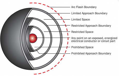
Why is the Electrical Boundary Different from the Limited and Restricted Approach Boundaries?
The safety boundary protects workers from heat and energy exposure during electrical work. In contrast, the limited and restricted approach boundaries are based on shock risks rather than energy exposure. The limited approach boundary marks the distance within which only qualified personnel can enter. In contrast, the restricted approach boundary requires additional controls and specialized protective gear due to the heightened risk of electric shock.
The boundary for energy exposure may extend farther than shock-related boundaries, especially in cases involving high energy levels. Both risk factors should be evaluated during a thorough risk assessment to ensure that workers are adequately protected from multiple hazards.
Calculating safe electrical boundaries based on energy levels is essential for maintaining workplace safety in environments with high electrical risks. Guidelines from IEEE 1584 and workplace electrical safety standards provide essential tools to calculate these distances accurately. Employing methods such as the incident energy analysis method or PPE categories can help ensure workers are protected from hazardous energy levels.
In addition, understanding how factors like electrode configuration, fault clearing time, and arc-rated clothing requirements impact boundaries is critical for designing safe systems. Proper planning and adherence to safety guidelines reduce the risk of injuries and equipment damage in the workplace, helping to create a safer environment for all involved.
Related Pages
What's the Arc Flash Boundary for 8 cal/cm²?