Understanding Ground Electricity

By R.W. Hurst, Editor

Ground Electricity

Ground electricity underpins grounding and earthing practices, managing earth potential and fault current. It ensures equipotential bonding, surge protection, and safety compliance per IEC/NEC standards for power systems, electronics, and lightning protection.


What Is Ground Electricity?

Ground electricity is the earth reference and return path that stabilizes systems and safely carries fault current.

✅ Provides low-impedance fault current paths to trip protection

✅ Uses earth electrodes, bonding, and grounding conductors

✅ Reduces touch voltage, EMI, and lightning surge damage


Understanding Ground Electricity 

Ground Electricity is a general term that is often used loosely to refer to “Bonding” (Safety Grounding) and “Earth Grounding”.  Personnel of major industries have often misinterpreted grounding to mean that anything in contact with the earth is considered to be grounded. For foundational context, see our overview on how electricity works to understand why grounding concepts are sometimes conflated.

Electrical Grounding is the reference zero for the electrical system.  When we talk about 120 Volts RMS, it represents 120 units above the zero electrical reference.  In residential settings, this reference is commonly tied to service equipment, as explained in our guide to home electricity and typical distribution practices.

Electrical Grounding is the reference zero for the electrical system and all the equipment should be at this same equipment potential plane. Maintaining that equipotential plane is central to electricity safety because it minimizes touch voltage hazards.

According to accident reports, most electrical accidents occur when the earth is used as the safety grounding system (Bonding).   These incidents underscore the broader dangers of electricity when protective paths are improperly designed.

Accident reports details the hazards of using earth as a safety grounding and the practice of electrical grounding the equipment through local grounds. (grounding each individual piece of equipment with a separate ground rod, driven into the earth).  Improper local grounds can also complicate fault clearing during a system electrical fault, increasing damage and downtime.

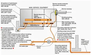
The best method for ensuring the safety of personnel is to use a “Bonding Conductor”. This conductor should be continuous, with sufficient ampacity and the lowest impedance path back to the circuit interrupting devices, which insures positive operation of the protective devices. A robust bonding network ensures rapid clearing of a ground fault by providing a low-impedance return path for protective devices.

Once a system that connects all the metallic frames of electrical equipment together has been established, then the grounding system must be placed at “Zero Reference Potential”.  The earth grounding electrode should have the lowest resistance value possible, preferably 5 ohms or less.   Coordinating equipment bonding with proper transformer grounding helps maintain stable reference potential across the installation.

This low resistance to earth ground electricity will limit the potential of the electrical system to earth (limiting the stresses placed on components such as switches, insulators and transformers).

It will also reduce the effects of static charges on the electrical system and will protect against lightning strokes, lightning induced voltages, and minimizes the effects of transient over-voltages.

Visit Our Electrical Grounding and Bonding Course 


Related Articles

Related News

Tidal Electricity From Wave Action

Tidal electricity converts predictable ocean tides into renewable energy using tidal turbines, barrages, and lagoons, delivering stable baseload marine power, efficient grid integration, low carbon emissions, and robust reliability through advanced hydrodynamics and power electronics.


What Is Tidal Electricity?

Tidal electricity generates grid power from ocean tides via turbines or barrages, providing predictable, low-carbon output.

✅ Uses tidal stream turbines, barrages, and lagoons

✅ Predictable output enhances grid stability and capacity planning

✅ Power electronics enable efficient conversion and grid integration


Tidal electricity is obtained by utilizing the recurring rise and fall of coastal waters. Marginal marine basins are enclosed with dams, making it possible to create differences in the water level between the ocean and the basins. The oscillatory flow of water filling or emptying the basins is used to drive hydraulic turbines which propel wave generators. As a specialized branch of hydroelectricity, tidal schemes convert predictable water level differences into dispatchable power.

The cyclical movement of seawater exemplifies how water electricity systems depend on fluid dynamics and site geometry.

Large amounts of wave generation could be developed in the world's coastal regions having tides of sufficient range, although even if fully developed this would amount to only a small percentage of the world's potential hydroelectric power. In global electricity production portfolios, tidal energy typically plays a niche role alongside other renewables.

Because installations are coastal and infrastructure-intensive, they can contribute to regional green electricity targets with long service lives.

It is produced by turbines operated by tidal flow. Many ideas for harnessing the tides were put forward in the first half of the 20th century, but no scheme proved technically and economically feasible until the development by French engineers of the plan for the Rance power plant in the Gulf of Saint-Malo, Brittany, built 1961–67. A dam equipped with reversible turbines (a series of fixed and moving blades, the latter of which are rotated) permits the tidal flow to work in both directions, from the sea to the tidal basin on the flood and on the ebb from the basin to the sea. The Rance plant has 24 power units of 10,000 kilowatts each; about seven-eighths of the power is produced on the more controllable ebb flow. The sluices fill the basin while the tide is coming in and are closed at high tide. Emptying does not begin until the ebb tide has left enough depth of fall to operate the turbines. Conversely, the turbines are worked by the incoming tide to the basin. With reversible bulb turbines, both ebb and flood flows generate electricity with high capacity factors during spring tides.

Compared with windmills for electricity, tidal turbines benefit from dense water flow that yields steadier torque.

The Soviet Union completed construction in 1969 of a plant of about 1,000 kilowatts on the White Sea. Other sites of interest for tidal power plants include the Bay of Fundy in Canada, where the tidal range reaches more than 15 m (49 feet). Although large amounts of power are available from the tides in favourable locations, this power is intermittent and varies with the seasons. Grid planners often pair tidal plants with storage and flexible resources used in electricity windmill operations to smooth variability.


Related Articles

View more

Electricity Meter

An electricity meter measures electrical energy consumption in homes, businesses, and industries. Also called a power meter or energy meter, it records kilowatt-hours, supports billing, monitors usage patterns, and ensures accurate tracking of electrical load.


What is an Electricity Meter?

An electricity meter is a vital device that utility companies use to measure the amount of electric power consumed by a household or business.

✅ Tracks consumption in kilowatt-hours (kWh) for accurate billing

✅ Monitors load, efficiency, and usage trends over time

✅ Essential for power distribution, energy management, and safety


It provides valuable data that helps both consumers and utility companies monitor power consumption, leading to improved energy management and more accurate billing.


How does an electricity meter work?

It measures the amount of power a household or business consumes, typically in kilowatt-hours (kWh). It records usage over time, allowing utility companies to bill customers accordingly.

Various types exist to suit different applications. The most common include:

  • Electromechanical meters (kWh) with a rotating aluminum disc that measures energy flow.

  • Digital meters that display consumption on an electronic screen.

  • Smart meters are advanced digital devices that automatically transmit usage data to the utility.

Smart meters are central to the smart grid, a modernized system designed to improve the efficiency and reliability of power distribution. With a smart device, consumers can access real-time information about their usage while utilities can implement time-of-use billing to encourage energy conservation during peak hours.


Net Metering & Solar Export Meters

For households with solar panels or other distributed energy sources, net recorders facilitate two-way power flow. They measure both the electrical energy consumed from the grid and the power exported back to it. This enables net metering programs, allowing consumers to earn credits or payments for surplus energy, making the adoption of renewable energy more cost-effective.


Communication & Technology Behind Smart Meters

Smart meters are part of the Advanced Metering Infrastructure (AMI), which utilizes communication networks, including RF mesh, cellular, and power line communication (PLC), to securely transmit usage data to the utility. This connectivity enables demand response programs, remote disconnections, and predictive maintenance, while providing consumers with detailed insights via apps and dashboards.


How do I read my Electricity Meter?

Reading your device may seem complicated, but it’s straightforward:

  • Electromechanical types use dials. Read each from left to right, taking the lower number if the pointer is between two digits.

  • Digital types display readings directly on an LCD screen, often cycling through consumption, demand, and tariff data.
    Some utilities also offer web portals or mobile apps that allow consumers to track their daily or hourly usage.


How can I check if my Electricity Meter is accurate?

To test accuracy, turn off all appliances and observe whether the recorder continues to record consumption. If it does, contact your utility for a professional inspection. Most utilities are required by regulation to maintain meter accuracy within specific tolerances defined by ANSI or IEC standards.

One innovation is the prepaid electricity meter, where consumers pay in advance for power. Once the credit is exhausted, the supply is disconnected until it is recharged. This approach enables households to budget more effectively and promotes conscious energy use.


Security & Privacy in Modern Meters

Electricity meter tampering is a significant concern for utilities. Attempts to reduce recorded consumption can lead to safety hazards and financial losses. Modern recorders include anti-tamper seals, encrypted communication, and intrusion detection to protect data integrity and ensure accurate billing. Utilities also conduct regular inspections to detect and prevent fraud.


What is a Smart Electricity Meter, and how does it differ?

It is a digital device that provides real-time usage data, supports two-way communication, and integrates with the smart grid. Unlike traditional recorders, it enables:

  • Automated reading

  • Dynamic tariffs and demand response

  • Access to consumer dashboards, apps, and alerts

These capabilities enhance billing accuracy, empower consumers to lower their energy costs, and facilitate a more flexible and sustainable grid.


Market Adoption & Trends

Smart meter adoption is growing worldwide. According to industry reports, over 1 billion smart meters have been deployed globally, with continued growth expected in North America, Europe, and Asia. In Canada, utilities like BC Hydro have rolled out smart meters to millions of customers, aiming for more reliable service and reduced outages.


Pros, Cons, and Challenges

Electricity meters offer several clear benefits, including accurate billing, improved energy management, integration with renewable energy sources, and reduced costs associated with manual meter reading. However, challenges include upfront costs, connectivity issues, consumer privacy concerns, and potential inaccuracies if meters drift out of calibration. Addressing these ensures the technology continues to deliver long-term benefits.


The Role of Electricity Meters in Energy Management

Understanding how they work, how to read them, and the different types available helps consumers make informed decisions about their energy usage. By verifying accuracy, adopting advanced technologies such as smart and prepaid meters, and utilizing apps and dashboards, households and businesses can gain greater control over their energy costs.

Ultimately, electricity meters are not just billing devices—they are gateways to improved efficiency, consumer empowerment, and a sustainable energy future.


Frequently Asked Questions


Can I read my smart meter remotely?

Yes. Most enable consumers to view their data via apps or online dashboards provided by their utilities.


How accurate are they?

They must comply with standards like ANSI C12 or IEC 62053, ensuring accuracy within strict tolerances.


What happens if it fails?

If it malfunctions, utilities are legally required to replace it and may use historical usage patterns for interim billing.


Related Articles


View more

Capacitance Explained

Capacitance: Understanding the Ability to Store Electricity

Capacitance is an essential concept in electrical circuits, and it describes the ability of a capacitor to store electrical energy. Capacitors are electronic components used in many circuits to perform various functions, such as filtering, timing, and power conversion. Capacitance is a measure of a capacitor's ability to store electrical energy, and it plays a crucial role in the design and operation of electrical circuits. This article provides an overview of capacitance, including its definition, SI unit, and the difference between capacitor and capacitance.


What is Capacitance?

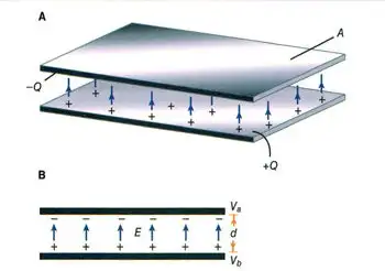
Capacitance is the ability of a capacitor to store electrical charge. A capacitor consists of two conductive plates separated by a dielectric material. The conductive plates are connected to an electrical circuit, and the dielectric material is placed between them to prevent direct contact. When a voltage source is applied to the plates, electrical charge builds up on the surface of the plates. The amount of charge that a capacitor can store is determined by its capacitance, which depends on the size and distance between the plates, as well as the dielectric constant of the material.

The energy storing capability of a capacitor is based on its capacitance. This means that a capacitor with a higher capacitance can store more energy than a capacitor with a lower capacitance. The energy stored in a capacitor is given by the formula:

Energy (Joules) = 0.5 x Capacitance (Farads) x Voltage^2

The ability to store energy is essential for many applications, including filtering, timing, and power conversion. Capacitors are commonly used in DC circuits to smooth out voltage fluctuations and prevent noise. They are also used in AC circuits to filter out high-frequency signals.


What is Capacitance and the SI Unit of Capacitance?

Capacitance is defined as the ratio of the electrical charge stored on a capacitor to the voltage applied to it. The SI unit of capacitance is the Farad (F), which is defined as the amount of capacitance that stores one coulomb of electrical charge when a voltage of one volt is applied. One Farad is a relatively large unit of capacitance, and most capacitors have values that are much smaller. Therefore, capacitors are often measured in microfarads (µF) or picofarads (pF).

The capacitance of a capacitor depends on several factors, including the distance between the plates, the surface area of the plates, and the dielectric constant of the material between the plates. The dielectric constant is a measure of the ability of the material to store electrical energy, and it affects the capacitance of the capacitor. The higher the dielectric constant of the material, the higher the capacitance of the capacitor.


What is the Difference Between Capacitor and Capacitance?

Capacitor and capacitance are related concepts but are not the same thing. Capacitance is the ability of a capacitor to store electrical energy, while a capacitor is an electronic component that stores electrical charge. A capacitor consists of two conductive plates separated by a dielectric material, and it is designed to store electrical charge. Capacitance is a property of a capacitor, and it determines the amount of electrical charge that the capacitor can store. Capacitance is measured in Farads, while the capacitor is measured in units of capacitance, such as microfarads (µF) or picofarads (pF).


What is an Example of Capacitance?

One example of capacitance is a common electronic component known as an electrolytic capacitor. These capacitors are used in a wide range of electronic circuits to store electrical energy, filter out noise, and regulate voltage. They consist of two conductive plates separated by a dielectric material, which is usually an electrolyte. The electrolyte allows for a high capacitance, which means that these capacitors can store a large amount of electrical energy.

Another example of capacitance is the human body. Although the capacitance of the human body is relatively small, it can still store a significant amount of electrical charge. This is why people can sometimes feel a shock when they touch a grounded object, such as a metal doorknob or a handrail. The capacitance of the human body is affected by several factors, including the size and shape of the body, as well as the material and proximity of the objects it comes into contact with.

View more

Electricity and Electrical Energy

Electricity powers modern engineering, driving circuits, voltage, current, and AC/DC power systems for transmission, distribution, and control. Engineers analyze resistance, impedance, and frequency, optimize grids, and integrate renewables with transformers, generators, and smart controls.


What Is Electricity?

Electricity is the flow of charge enabling energy conversion, signal transmission, and power control across circuits.

✅ Quantified by voltage (V), current (A), and power (W)

✅ Governed by Ohm's Law, Kirchhoff's Laws, and Maxwell's equations

✅ Transmitted via grids using AC, transformers, and protection


Electricity is a manufactured product. It is not something you pump out of the ground or mine or collect from the sun or wind. For a clear primer on definitions and units, visit what electricity is to ground these ideas.

Electric power is manufactured from a rotating machine that we call an electrical generator. After it is generated, (manufactured) it is then delivered through copper wires to where it is utilized If you want to see how turbines and alternators convert motion into power, explore the electricity generator to understand key components and operation.

Electricity - most people don't understand what it is. They just turn on the light switch or start the appliance or push the button and something works. It's only when there is no electric power available that we start to consider the importance of it in our daily personal and working lives. A step-by-step explanation of fields, voltage, and current is outlined at how electricity works for readers new to the topic.

But the invention of the machine to generate power is right next to the invention of the printing press in the list of major contributions to the advancement of human civilization. For context on pioneers from Faraday to Tesla, review who invented electricity to connect invention with modern grids.

Without it, we would be burning wood and coal to heat our homes and businesses and using oil and candles to light our way in the dark. That is the way it was for humans civilization for countless centuries. Only since the invention of the electric generator have humans been able to advance in every aspect of modern life. In fact, modern living is defined by electric power. This shift from fuels to electrons is traced in the history of electricity to show how infrastructure reshaped society.

We have assembled a series of pages in our web site to help you to understand the business of electricity - how it works and how it is used. To dive deeper into fundamentals before the business aspects, start with electricity: how it works for a concise technical overview.

We hope that you can use this information to better understand the technology and issues behind the manufacturing of electric power. Further reading on thermal, hydro, and renewable pathways is available at how electricity is generated to see how manufacturing methods compare.


Related Articles

View more

Electricity Generator

Electricity generator converts mechanical energy to electrical power via electromagnetic induction using a prime mover, alternator, stator, and rotor, delivering regulated AC/DC output, high efficiency, and stable voltage and frequency.


What Is an Electricity Generator?

An electricity generator converts mechanical energy to electric power using electromagnetic induction, AC or DC.

✅ Converts rotational torque into regulated AC or DC output

✅ Uses stator, rotor, and excitation for voltage regulation

✅ Applied in power plants, gensets, microgrids, and renewables


An Electricity Generator can create electricity by converting mechanical energy into electrical current that can be used in electrical systems. Wind turbines house such generators to convert the kinetic energy of wind into power that can feed power grids. involve the production of electrons that are a part of every atom,. Electricity is what results when electrons are flowing through a conductor. Ultimately, all that is needed to generate electricity is a metal wire for a conductor and a catalyst to start the electrically charged electrons flowing. You see, unlike natural gas and other fossil fuels that are mined from the Earth, electricity is a manufactured product. Most generators operated by electric utilties are alternating current (ac) generators but there are still some direct current (dc) generators in existence. For a clear primer on charge, current, and how generators relate to these basics, see what is electricity to ground these concepts.

Alternating current is easily generated by means of a rotating magnet windings in a coil of wire, or by a rotating coil of wire inside a powerful magnet. In either case, the ac appears between the ends of the length of wire. This takes place in an electricity generator, which was invented by Michael Faraday. A portable generator can be used as backup power during a power outage. If you want a step-by-step view of induction and circuit behavior, consult how electricity works for context beyond this overview.

The ac voltage that a generator (motor) can develop depends on the strength of the magnets field, the number of turns in the wire coil, and the speed at which the magnet or coil rotates. The ac frequency depends only on the speed of rotation. Normally, for utility ac, this speed is 3,600 revolutions per minute (rpm), or 60 complete revolutions per second (rps), so that the frequency is 60 Hz. Design choices that set coil turns, flux, and rotational speed are discussed in how electricity is generated with practical examples.

When a load, such as a light bulb or heater, is connected to an ac generator, it becomes more difficult to turn the generator. The more power needed from a generator, the greater the amount of power required to drive it. This is why it is not possible to connect a generator to, for instance, your stationary bicycle, and pedal an entire city into electrification. There's no way to get something for nothing. The electrical power that comes out of a generator can never be more than the mechanical power driving it. In fact, there is always some energy lost, mainly as heat in the generator. Your legs might generate 50 W of power to run a small radio, but nowhere near enough to provide electricity for a household. Realistic scenarios for human power and small prime movers are outlined in generate electricity to help size expectations.

The efficiency of a generator is the ratio of the magnet generate power output to the driving power, both measured in the same units (such as watts or kilowatts), multiplied by 100 to get a percentage. No generator is 100 percent efficient. But a good one can come fairly close to this ideal. Typical loss mechanisms and efficiency ranges across technologies are compared in electricity generation for further reading.

At power plants, the power generators can be huge. Each one can be as big as a house. In a power plant, each electricity generator is driven by a massive turbine. Often, steam drives the turbine, and the steam is obtained via heat derived from natural energy source, like falling water. Capacity factors, fuel choices, and turbine types are covered in electricity production to illustrate real-world plant operation.

There are many different sources of electricity and many different ways electricity can be produced and consumed. For instance, modern wind turbines are explained in electricity windmill with details on siting, capacity, and grid integration.


Related Articles

View more

Kirchhoff's Law

Kirchhoff's Law, comprising the Current Law (KCL) and Voltage Law (KVL), governs electrical circuits by ensuring charge conservation and energy balance, essential for analyzing current flow, voltage drops, and network behaviour.


What is Kirchhoff's Law?

Kirchhoff's law is an essential principle in the analysis of electrical circuits, enabling a comprehensive understanding of the behaviour of complex circuits.

✅ Defines relationships between currents and voltages in electrical circuits

✅ Ensures conservation of charge (KCL) and energy (KVL) in networks

✅ Essential for analyzing and solving complex circuit problems

It consists of two fundamental rules, Kirchhoff's Current Law (KCL) and Kirchhoff's Voltage Law (KVL), which are intrinsically linked to other electricity laws, such as Ohm's law.  Kirchhoff’s Law works closely with Ohm’s Law Formula to calculate voltage drops, currents, and resistance in electrical networks.

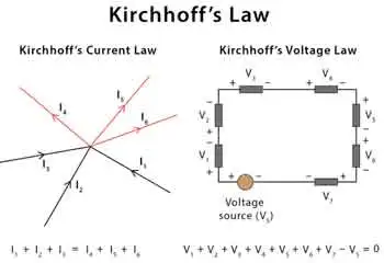
Kirchhoff's Current Law (KCL) - Also known as the first Kirchhoff's law or Kirchhoff's junction rule, KCL states that the sum of the currents entering a junction in a circuit is equal to the sum of the currents leaving the junction. Mathematically, it can be expressed as:

ΣI_in = ΣI_out

KCL is based on the principle of the conservation of charge, asserting that charge can neither be created nor destroyed. In practical terms, KCL means that, at any given point in a circuit, the total current entering must equal the total current leaving, ensuring a continuous flow of electric charge. Understanding Basic Electricity provides the foundation for applying Kirchhoff’s Current Law and Voltage Law to real-world circuit analysis.

Kirchhoff's Voltage Law (KVL) - Also known as the second Kirchhoff's law or Kirchhoff's loop rule, KVL states that the sum of the voltage gains and losses (potential differences) around any closed loop in a circuit is zero. Mathematically, it can be expressed as:
ΣV_rise = ΣV_drop

KVL is based on the principle of the conservation of energy, indicating that energy cannot be created or destroyed but can only be converted from one form to another. In electrical circuits, KVL implies that the total voltage supplied in a loop equals the total voltage drop across all components, ensuring that energy is conserved. Accurate circuit calculations require a clear grasp of Electrical Resistance and how it impacts voltage distribution across components.


Relation to Other Electricity Laws

The most significant connection between Kirchhoff's and other electricity laws is Ohm's law, which defines the relationship between voltage, current, and resistance in an electrical circuit. Ohm's law can be expressed as:

V = IR

When analyzing a circuit using Kirchhoff's laws, Ohm's law is often employed to calculate unknown quantities such as voltage drops, currents, or resistance values. By combining Kirchhoff's laws with Ohm's law, a complete understanding of the behaviour of electrical circuits can be achieved, facilitating efficient design, troubleshooting, and optimization. Applying Kirchhoff’s principles is easier when you understand key Electrical Terms used in engineering and troubleshooting.


History

Gustav Robert Kirchhoff, a German physicist, made significant contributions to understanding electrical circuits by establishing two fundamental laws: Kirchhoff's Voltage Law (KVL) and Kirchhoff's Current Law (KCL). These laws are essential tools for circuit analysis, enabling engineers to design and troubleshoot electrical networks efficiently. In addition to resistance, Capacitance plays a vital role in determining circuit behavior, especially in AC systems.

KVL, also known as the loop rule, states that the algebraic sum of all the voltages around a closed loop equals zero. This principle is derived from the conservation of energy, which ensures that no energy is lost within a closed system. In essence, KVL states that the energy supplied to a circuit is equal to the energy consumed by the components in that circuit. Therefore, when solving problems using KVL, it is essential to consider voltage drops across resistive elements like resistors and voltage rises due to sources like batteries or generators.

On the other hand, KCL, or the junction rule, states that the algebraic sum of currents entering a junction (node) in a circuit is equal to the sum of currents leaving the same junction. This law is a consequence of the conservation of charge, which posits that charge cannot be created or destroyed within an electrical circuit. KCL ensures that the total charge entering and leaving a node remains constant, with the currents (I1, I2, I3, I4, I5) balancing each other. Knowledge of Voltage Drop is essential when using KVL to assess energy losses in electrical circuits.

The significance of these laws in electrical networks lies in their versatility, as they can be applied to a wide range of circuits, from simple series and parallel circuits to more complex electrical networks. Kirchhoff's laws can be employed in conjunction with Ohm's Law, which states that the current through a conductor is proportional to the voltage across it and inversely proportional to its resistance. Using Kirchhoff's and Ohm's Law, engineers can analyze various aspects of a circuit, including voltage drops, current flow, and power distribution.

When analyzing series and parallel circuits, his laws offer valuable insight into the behaviour of electrical components. In series circuits, the current remains constant throughout the entire loop, while the voltage drops across each resistor are proportional to their respective resistances. The voltage across each branch is constant in parallel circuits, but the current is divided among the parallel resistors according to their resistances. By applying KVL and KCL to these configurations, engineers can determine the optimal arrangement of components for a given application.

To illustrate the application of his laws, consider a simple example. Imagine a circuit with a battery, two resistors in series, and a capacitor in parallel with the second resistor. By applying KVL and KCL, we can determine the voltage drop across each resistor, the current flow through each branch, and the voltage across the capacitor, enabling us to analyze the circuit's behaviour under various conditions.

Despite their usefulness, his laws have some limitations and assumptions. For instance, they assume that the components in a circuit are ideal, meaning they have no internal resistance or capacitance. Additionally, they don't account for the effects of electromagnetic fields or the finite speed of signal propagation in AC circuits. However, these limitations are often negligible in many practical applications, as they only marginally impact circuit performance. For a deeper historical context, explore the History of Electricity and the contributions of Gustav Kirchhoff to modern circuit theory.


Related Articles


View more

Sign Up for Electricity Forum’s Newsletter

Stay informed with our FREE Newsletter — get the latest news, breakthrough technologies, and expert insights, delivered straight to your inbox.

Electricity Today T&D Magazine Subscribe for FREE

Stay informed with the latest T&D policies and technologies.
  • Timely insights from industry experts
  • Practical solutions T&D engineers
  • Free access to every issue

Download the 2025 Electrical Training Catalog

Explore 50+ live, expert-led electrical training courses –

  • Interactive
  • Flexible
  • CEU-cerified