Electricity Production

Electricity Production Explained

Electricity production converts primary energy into power via thermal, hydro, wind, and solar systems, optimizing efficiency, capacity factor, grid stability, transmission reliability, and emissions through turbines, generators, inverters, and advanced SCADA control.


What Is Electricity Production?

Electricity production converts energy to electric power, prioritizing efficiency, safety, and grid reliability.

✅ Conversion via turbines, generators, inverters, and transformers

✅ Control with SCADA, protective relays, and load-frequency regulation

✅ Optimization of efficiency, capacity factor, and emissions


Electricity Production continues to grow around the world, from a variety of energy power sources. In terms of world electricity generation, the US Department of Energy predicts advances strongly from 2004 to 2030. Global production increases by 2.4 percent per year over the projection period, from 16,424 billion kilowatthours in 2004 to 30,364 billion kilowatthours in 2030. Much of the growth in electric power demand is projected for nations outside the OECD. Although the non-OECD nations consumed 26 percent less electricity than the OECD nations in 2004, total generation in the non-OECD region in 2030 is projected to exceed generation in the OECD by 30 per cent. For context, the International Energy Outlook provides a concise overview of electricity generation trends worldwide today.

Total electricity demand in the non-OECD nations is expected to grow from 2004 to 2030 at an annual rate that is nearly triple the rate of growth for electricity demand in the OECD. The difference reflects the relative maturity of electricity infrastructure in the more developed OECD region, as well as the expectation that populations in the OECD countries generally will grow slowly or decline over the next 25 years. In addition, fast-paced growth in the developing non-OECD economies translates to rising standards of living and robust growth in consumer demand for lighting and appliances. Total electricity generation in the non-OECD region increases by an average of 3.5 percent per year in the IEO2007 reference case, as compared with a projected annual growth rate for OECD electricity generation that averages 1.3 per cent per year from 2004 to 2030. Among the energy end-use sectors, the most rapid growth in total world demand for electricity is projected for the buildings (residential and commercial) sectors.

Understanding the diversity of sources of electricity helps explain regional growth patterns in demand.

In Power plants, electricity Production involves the generation or creation of electric power, using rotating turbines attached to an energy generator. This mechanical manufacturing of electricity produces most commercially available electricity. Turbines are driven by a fluid which acts as an intermediate energy carrier. The fluids typically used are:

For readers new to plant design, this primer on how electricity is generated clarifies the roles of turbines, generators, and working fluids.

  • steam - Water is boiled by nuclear fission or the burning of fossil fuels (coal, natural gas, or petroleum). Some newer plants use the sun as the heat source: solar parabolic troughs and solar power towers concentrate sunlight to heat a heat transfer fluid, which is then used to produce steam. Another renewable source of heat used to drive a turbine is Geothermal power. Either steam under pressure emerges from the ground and drives a turbine or hot water evaporates a low boiling liquid to create vapour to drive a turbine.
  • water - Turbine blades are acted upon by flowing water, produced by hydroelectric dams or tidal forces,
  • wind - Most wind turbines generate electricity from naturally occurring wind. Solar updraft towers use wind that is artificially produced inside the chimney by heating it with sunlight.
  • hot gases - Turbines are driven directly by gases produced by the combustion of natural gas or oil. Combined cycle gas turbine plants are driven by both steam and gas. They generate power by burning natural gas in a gas turbine and use residual heat to generate additional electricity generation from steam. These plants offer efficiencies of up to 60%.

Hydropower and tidal technologies illustrate how water-based electricity remains a cornerstone in many regions.

Various other technologies have been studied and developed for power generation. Solid-state generation (without moving parts) is of particular interest in portable applications. This area is largely dominated by thermoelectric (TE) devices, though thermionic (TI) and thermophotovoltaic (TPV) systems have been developed as well. Typically, TE devices are used at lower temperatures than TI and TPV systems. Piezoelectric devices are used for power generation from mechanical strain, particularly in power harvesting. Betavoltaics are another type of solid-state power generator which produces electricity from radioactive decay. Beyond conventional turbines, a range of alternative electricity options are being explored for niche and distributed applications.

Fluid-based magnetohydrodynamic (MHD) electricity generation has been studied as a method for extracting electrical power from nuclear reactors and also from more conventional fuel combustion systems. These advanced concepts broaden our understanding of how we generate electricity under extreme conditions.

Electrochemical is also important in portable and mobile applications. Currently, most electrochemical power comes from closed electrochemical cells ("batteries"), which are arguably utilized more as storage systems than generation systems, but open electrochemical systems, known as fuel cells, have been undergoing a great deal of research and development in the last few years. Fuel cells can be used to extract power either from natural fuels or from synthesized fuels (mainly electrolytic hydrogen) and so can be viewed as either generation systems or storage systems depending on their use. In many systems the electricity generator ultimately interfaces with inverters and controls for grid integration.


Related Articles

Related News

Static Electricity

Static electricity is a fascinating phenomenon that can be both awe-inspiring and dangerous. Understanding its basic concepts, including the movement of charged particles and the causes of positive and negative charge imbalance, is crucial in preventing potential hazards. By taking preventive measures such as grounding equipment and surfaces, using anti-static materials, and increasing humidity, we can avoid the buildup of static charges and protect ourselves and our environment from its hazards. It is also important to understand the potential dangers and take appropriate precautions, particularly when working with flammable or explosive materials. With this knowledge, we can safely harness the power and explore its many fascinating properties.


What is static electricity?

It results from the movement of charged particles, called electrons and particles called protons, which make up the atoms of matter. Atoms are made up of protons, neutrons, and electrons. Protons have a positive charge, electrons have a negative charge, and neutrons have no charge. In most atoms, the positive charge of the protons is balanced by the negative charge of the electrons, resulting in a neutral object.

However, when two objects come in contact, the extra electrons from one object may transfer to the other, creating a charge imbalance. This results in one object having a positive charge and the other having a negative electric charge. These charges repel, and when the objects are separated, they retain the charges, creating a static charge.


What causes static electricity?

As previously mentioned, it is caused by the movement of charged particles. When there is a charge imbalance between two objects, it can create a static charge. This can occur through friction, conduction, or induction.

Friction occurs when two objects rub against each other, causing electrons to transfer from one object to the other. For example, this is why you may experience it when you rub a balloon against your hair, causing your hair stand to stand up.

Conduction occurs when two objects come in contact and transfer electrons between them. For example, when you touch a doorknob, you may receive a static shock if the doorknob is charged.

Induction occurs when a charged object is brought near a neutral object, causing a charge to be induced in the neutral object.


How does static electricity work?

It creates a charge imbalance between two objects, resulting in one object having a positive charge and the other having a negative charge. These charges repel each other, and when the objects are separated, they retain the charges, creating a static charge.

When a charged object comes in contact with a neutral object, the charge may transfer, resulting in a static shock. This occurs when the charge imbalance is released as a spark. Static shocks are usually harmless but can sometimes be dangerous, particularly in hazardous environments.


Can static electricity hurt you?

While it is usually harmless, it can sometimes be dangerous. A static shock occurs when a charged object comes in contact with a person or object that is not charged. The shock results from the charge imbalance being released as a spark. The shock can be uncomfortable, and in rare cases, it can cause serious injury, mainly if it occurs in a hazardous environment, such as around flammable materials.


What are the dangers of static electricity?

It can be dangerous in certain situations, such as when working with flammable or explosive materials. A spark from it can ignite flammable gases or vapours, leading to fires or explosions. In industrial settings, it is important to take precautions to prevent the buildup of static charges and to discharge any charges that may occur.


How do you discharge static electricity?

There are several ways to discharge it, including:

  • Grounding: Connecting the charged object to a ground source such as the earth, which dissipates the excess charge.
  • Anti-static materials: Wearing clothes made of anti-static materials or using anti-static sprays can prevent the buildup of static charges.
  • Humidification: Increasing the humidity in a room can help reduce a buildup by adding moisture to the air.
  • Use of ionizers: Ionizers can neutralize it by releasing negative ions into the air.
  • Proper grounding of equipment: Ensuring that all equipment and surfaces are properly grounded can prevent the buildup of static charges.


How can you prevent static electricity?

Preventing buildup involves taking several steps, such as:

  • Using anti-static materials: Clothing made of anti-static materials or anti-static sprays can prevent the buildup of static charges.
  • Grounding: Ensuring that all equipment and surfaces are properly grounded can prevent the buildup of static charges.
  • Humidification: Increasing the humidity in a room can help reduce a buildup by adding moisture to the air.
  • Proper handling of flammable materials: When working with flammable or explosive materials, it is important to take proper precautions to prevent a buildup and discharge of any charges.
  • Using equipment designed for use in hazardous environments: Equipment designed for use in hazardous environments is designed to prevent a buildup and sparks from occurring.

In addition to these preventive measures, it is important to understand the basics of static electricity and the factors that contribute to its buildup. This knowledge can help individuals take steps to avoid buildup and prevent any potential hazards.


Van de Graaff Generator: An Experiment with Static Electricity

One fascinating example of this is the Van de Graaff generator. This device was invented in 1929 by Robert J. Van de Graaff and is used to generate high voltages of static electricity. The generator transfers electrons from a moving belt to a metal sphere, creating a charge imbalance between the two objects.

This charge imbalance creates a strong electric field, which can be used to demonstrate various phenomena. For example, the electric field can cause hairs on a person's head or arm to stand up due to the repulsion between the positively charged hair and the positively charged metal sphere.


View more

Wattmeters – Power Measurement

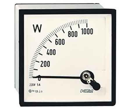
Wattmeters measure electrical power in watts, monitoring energy use in industrial power systems. They provide accurate active power readings for efficiency and load management, utilizing voltage and current measurements to achieve precise results.


What are Wattmeters?

Wattmeters are instruments used to measure electrical power. They:

✅ Measure active electrical power in watts for various applications.

✅ Are used in industrial, commercial, and residential energy monitoring.

✅ Help optimize efficiency, manage loads, and ensure system safety.

A wattmeter measures instantaneous (or short-term) electrical power in watts, while a watthour meter accumulates that power over time and reports energy used (e.g. in kWh). Energy meters and smart meters extend this concept by recording consumption continuously for billing, load analysis, and energy audits.


Working Principle of Wattmeters

Electrical power is calculated using the formula:

P = E × I

Where:

  • P = Power in watts

  • E = Voltage in volts

  • I = Current in amperes

In DC circuits, watts are sometimes expressed as volt-amperes (VA). In AC circuits, wattmeters measure true (or active) power, taking into account the power factor to compensate for phase differences between voltage and current. Unlike reactive power (measured in kvar) or apparent power (measured in kVA), active power is the usable portion that does real work. This relationship is often represented in the power triangle, where vector analysis explains how apparent, reactive, and active power interact.


Construction and Internal Components

A typical wattmeter consists of two main coil assemblies:

  1. Current Coil (CC)

    • Heavy-gauge copper wire with low resistance.

    • Connected in series with the load to carry the circuit current.

  2. Voltage Coil (VC)

    • Fine-gauge wire with high resistance.

    • Connected in parallel with the load to measure voltage.

The electrodynamometer, commonly referred to as a dynamometer wattmeter, is a classic analog device that operates on the principle of a motor. The interaction between the magnetic fields of the current and voltage coils produces a torque proportional to the power, causing the pointer to move over a calibrated scale. Understanding wattmeter principles is a foundation of basic electricity training, helping learners connect theory to practical power measurement.


Figure 1 – Construction of a dynamometer wattmeter showing current and voltage coil arrangement.


Types of Wattmeters

  • Analog/Dynamometer – Durable, reliable, suited for laboratory and field measurements.

  • Digital – Higher accuracy, data logging, and integration with monitoring systems.

  • Clamp-on  – Measure power without breaking the circuit, ideal for quick diagnostics.

  • Specialized  – Designed for RF power, audio power, or other niche applications.

In three-phase systems, wattmeters are often applied in accordance with Blondel’s theorem, which specifies the number of measurement elements required in multi-phase circuits. They are frequently used in conjunction with 3 phase electricity concepts to ensure balanced load distribution and optimal system efficiency.


Fig. 2. Power can be measured with a voltmeter and an ammeter.


Measuring Power in DC and AC Circuits

In DC circuits, power measurement can be as simple as multiplying voltage and current readings from separate meters.

Example:

If a circuit operates at 117 V DC and draws 1 A, the power is:

P = 117 × 1 = 117 W

In AC systems, especially with reactive or distorted loads, a wattmeter is essential because voltage and current may not be in phase. The device automatically accounts for the phase angle, providing accurate true power readings. Advanced digital wattmeters also compensate for harmonic distortion and poor waveform quality, providing more reliable measurements than older analog designs.

By measuring energy transfer in circuits, they also relate to other power measurement instruments such as ammeters, voltmeters, and multimeters, which measure supporting parameters needed for complete electrical analysis. Accurate wattmeter readings are crucial for diagnosing performance issues in 3-phase power networks, where the relationships between voltage and current are critical. By measuring energy transfer in circuits, they help explain fundamental laws of electromagnetism, such as Ampère’s Law, which underpins the interaction between current and magnetic fields.


Fig. 2. Power can be measured with a voltmeter and an ammeter.


Practical Examples and Load Considerations

A household iron may consume 1000 W, drawing 8.55 A at 117 V.

A large heater may draw 2000 W, or 17.1 A, potentially overloading a 15 A breaker.

In industrial settings, watt meters help prevent equipment overloading, reduce downtime, and improve energy efficiency.


Modern Wattmeter Applications

Today’s wattmeters are often part of smart energy monitoring systems that:

  • Track energy consumption over time.

  • Integrate with SCADA and IoT platforms.

  • Enable predictive maintenance through power trend analysis.

  • Support compliance with energy efficiency regulations.


Accuracy, Standards, and Advanced Considerations

Measurement accuracy is a crucial factor in determining wattmeter performance. Devices are often classified by a class of accuracy, with error limits defined by international standards such as IEC, ANSI, or IEEE. Regular calibration and testing procedures ensure watt meters continue to deliver reliable results in both laboratory and field conditions.

Modern digital watt meters feature true RMS measurement, which accurately captures distorted waveforms caused by nonlinear loads. This is especially important in power systems where harmonic distortion is present. In commercial and industrial environments, accurate wattmeter data support energy audits, load analysis, and regulatory compliance, making them indispensable tools for engineers and facility managers. Wattmeter usage is closely linked to the fundamentals of electrical energy, enabling precise monitoring for efficiency and cost control.


Key Advantages of Wattmeters

  • Accurate real-time power measurement.

  • Enhanced energy management and cost savings.

  • Improved system reliability through overload prevention.

  • Compatibility with both AC and DC systems.

Wattmeters remain a vital tool for measuring and managing electrical power. Whether in a simple residential circuit, a commercial energy audit, or a high-tech industrial monitoring system, they ensure that electrical systems run efficiently, safely, and cost-effectively. As technology advances, digital and networked wattmeters continue to expand their role, integrating into smart grids and energy-optimized infrastructures. 


Related Articles


View more

Electricity Supplier - Make The Right Choice

Electricity supplier delivers power via transmission and distribution networks, managing tariffs, load forecasting, SCADA, and power quality, integrating renewables, smart meters, and demand response to ensure grid reliability, compliance, and efficient kWh billing.


What Is an Electricity Supplier?

An electricity supplier procures and delivers power, manages tariffs, and ensures grid reliability and power quality.

✅ Energy procurement and wholesale market participation

✅ Distribution coordination, SCADA monitoring, and outage management

✅ Tariff design, metering, billing, and power quality compliance


Who is my electricity supplier?

In Canada and the United States, it’s easy to learn which energy provider serves your property or residence. It depends on whether you are trying to find your electricity and natural gas supplier. Sometimes, homes and businesses have the power to choose their energy service utility company and the products and service they provide. Customers are free to choose. It's a competitive energy marketplace. For a plain-language primer on infrastructure, see the electricity supply overview to understand typical delivery steps.

If you use both services, your property might have the same local distribution company for both fuels, – commonly known as a "duel fuel supplier". But if your utility records are stored separately, you might need to more research to learn who supplies your natural gas services and your electricity services separately. If you are curious where the power originates, this guide to how electricity is generated explains common fuel sources and grid integration.


Here is a list of accredited Electricity Suppliers in Canada

https://www.ic.gc.ca/eic/site/mc-mc.nsf/eng/lm00525.html

Market dynamics can vary by province, and recent electricity demand trends in Canada help explain seasonal shifts in offers.


Here is a list of accredited Electricity Suppliers in the United States.

https://www.electricchoice.com/blog/25-top-providers-part-1/

When comparing providers, consult current electricity price benchmarks to contextualize quoted rates.


Who can supply electricity?

All electricity supplier companies must have a licence from the Office of Gas and Electricity Markets (Ofgem). One of the licence conditions is that a  company must produce codes of practice on:

Although the codes of practice are not legally enforceable, they will be useful when negotiating with a company and any breach should be reported to governmental regulatory authorities. Understanding the basics in this introduction to what electricity is can make those obligations clearer.


Choosing an electricity supplier

You can change your company if you wish. If you are considering changing your company you should be aware that the pricing structures, services offered and policies will differ between the different companies.You should carefully check the information and contracts of the competing electricity suppliers, and compare these to your current terms, to make sure that you choose the best deal for your needs. A lot depends on your gas bills or electricity bill, and your location by postal code. You can also estimate bill impacts by applying tips from this guide on how to save electricity while comparing plans.


Dual fuel offers

Dual fuel is the supply of gas and electricity by the same company. Some gas and electricity suppliers are licensed separately by Ofgem to supply customers with both fuels. Some companies will supply both fuels under one contract, while others will give one contract for gas and another for electricity. For households with high usage, reviewing your typical electricity power consumption patterns can reveal whether dual fuel makes financial sense.

Electricity Suppliers who make dual offers will often give a discount off the total bill as they can make administrative savings by issuing combined bills and collecting combined payments. However, this does not necessarily mean that the cost of gas and electricity

  • procedures for complaints
  • payment of bills, arrangements for dealing with arrears and prepayment meters
  • site access procedures
  • energy efficiency advice
  • services for older, disabled and chronically sick people. As part of this code of practice, the company must keep a register of these people and provide services to help those who are blind and partially sighted or deaf or hearing impaired. Especially during a power outage, it is important that these customers are restored asap.The customer may have to pay for some of these services.
    • how you will be charged for your electricity supply. Some companies may make a fixed standing charge and then a unit charge for the amount of electricity used; an company may not make a standing charge, but charge a higher unit price
    • whether different charges apply to different periods during the day
    • if cheaper prices are offered for particular payment methods, for example, if you pay by direct debit
    • what service standards each company is offering, for example, for repairs, extra help for older or disabled customers.All electricity suppliers must keep a list of their customers who ask to be identified as pensioners, chronically sick or disabled.The electricity supplier must tell all its customers that it keeps such a list and give information on how customers can be added to the list
    • the company's policies, for example, on debt and disconnection.


Related Articles

View more

Watthour Meter Explained

A watthour meter measures electrical energy consumption in kilowatt-hours (kWh) for residential, commercial, and industrial applications, ensuring accurate billing, energy management, and compliance with utility standards.


What is a Watthour Meter?

✅ Measures total electrical energy in kilowatt-hours (kWh) over time

✅ Supports accurate billing, energy monitoring, and demand analysis

✅ Used in residential, commercial, and industrial revenue metering


Advancements in Watthour Meter Technology and Energy Measurement

Watthour meter technology plays a crucial role in modern electrical engineering and maintenance by providing accurate measurement and monitoring of energy consumption. These devices are indispensable for managing energy efficiency, optimizing power distribution, and ensuring compliance with regulatory standards. For electrical professionals, understanding how they operate and are maintained is essential to minimize energy losses and enhance the reliability of electrical systems. With the growing demand for precise energy data in both residential and industrial applications, staying informed about advancements in watthour meter technology is more important than ever. Understanding how a watthour is calculated helps clarify how a watthour meter tracks total energy usage for accurate billing. 


How Induction Type Single Phase Watt Hour Meters Work

Induction type meters, commonly used as single phase watt hour meters, provide accurate measurement of electrical energy consumption in residential and small commercial installations.

Your electric utility is not too interested in how much power you're consuming for one ap­pliance or even how much power a single household is drawing at any given time. By far the greater concern is the total energy that is used over a day, a week, a month or a year. Electrical energy is measured in watt-hours or, more commonly for utility pur­poses, in kilowatt-hours (kWh). The device that measures this consumption is the watt-hour meter or kilowatt-hour meter. For a deeper understanding of the units used in metering, see our guide on electrical energy and how it is measured in kilowatt-hours.

The most common method for measuring electrical energy is by using a small elec­tric motor device, whose speed depends on the current, and thereby on the power at a constant voltage. The number of turns of the motor shaft, in a given length of time, is di­rectly proportional to the number of watt hours consumed. The motor is placed at the point where the utility wires enter the house, apartment or building. This is usually at a point where the voltage is 234 V. This is split into some circuits with 234 V, for heavy-duty appliances such as the oven, washer and dryer, and the general household circuits for lamps, clock radios and television sets. The principles behind watthour meters are closely tied to basic electricity and the relationship between active power and time.


Understanding the Spinning Disk in Electromechanical Watthour Meters

You've surely seen the little disk in the utility meter going around and around, sometimes fast, other times slowly. Its speed depends on the power you're using. The total number of turns of this little disk, every month, determines the size of the bill you will get, as a function also, of course, of the cost per kilowatt hour for electricity.

Kilo-watt-hour meters count the number of disk turns by means of geared, rotary drums or pointers. The drum-type meter gives a direct digital readout. The pointer type has several scales calibrated from 0 to 9 in circles, some going clockwise and others go­ing counterclockwise. Mechanical and electronic meters both rely on the concepts of electrical resistance and current to provide precise readings.


How to Read a Pointer-Type Watthour Meter Accurately

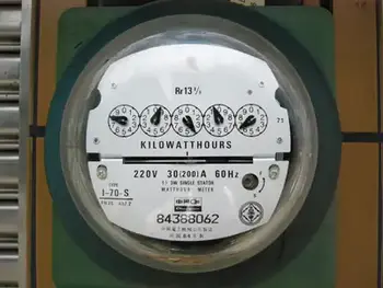
Reading a pointer-type utility meter is a little tricky because you must think in whatever direction (clockwise or counterclockwise) the scale goes. An example of a pointer-type utility meter is shown in Fig. 3-11. Read from left to right. For each little meter, take down the number that the pointer has most recently passed. Write down the rest as you go. The meter in the figure reads 3875 kWh. If you want to be really pre­cise, you can say it reads 3875-1/2 kWh. To place watt hour metering in historical context, explore our history of electricity page and learn how early meters evolved into today’s advanced devices.


Fig. 3-11 An example of a utility kilo-watthour meter. The reading is a little more than 3875 kWh.


Related Articles


View more

Difference between AC and DC Electricity

Difference Between AC and DC explains alternating current vs direct current, waveform shape, frequency, voltage, polarity, rectification, inversion, power transmission, and typical uses in electronics, grids, batteries, and power supplies.


What Is the Difference Between AC and DC?

AC reverses direction and frequency; DC is unidirectional. They differ in waveform, voltage, and uses.

✅ AC: sinusoidal waveform; DC: steady line

✅ AC frequency varies by region (50/60 Hz)

✅ Rectifiers convert AC to DC; inverters convert DC to AC


The difference between AC and DC electrical currents is crucial to understand their unique characteristics and diverse applications. By examining the electron flow, voltage variation, power transmission, and safety implications of each current type, we can better appreciate the complex electrical systems that power our daily lives. This comprehensive article offers a deeper understanding of the fundamental distinctions between AC and DC currents, revealing their significance in electricity. For foundational context, see a concise definition of electricity that frames these distinctions clearly.


Two primary types of current dominate the world of electricity: alternating current (AC) and direct current (DC). To understand the difference, we need to explore their unique characteristics, applications, and the principles behind their operation. This comprehensive guide will delve into the details of each electrical current, providing examples and formulas for greater clarity. A broader primer on charge flow is available in this overview of current electricity for readers building fundamentals.

AC (alternating current) and DC (direct current) differ fundamentally in the flow of electrons. In an alternating current, the flow of electrons periodically reverses direction, following a sinusoidal waveform. The waveform is described by the formula V(t) = Vm * sin(2 * π * f * t), where Vm is the maximum voltage, f is the frequency, and t is time. On the other hand, in a direct current, the flow of electrons is constant and unidirectional, resulting in a steady voltage level. For a deeper explanation of sinusoidal behavior, consult this alternating current resource to connect theory with practice.


What is AC electrical current, and how is it measured?

AC (alternating current) is an electrical current in which the flow of electrons periodically reverses direction. Unlike direct current (DC), where the electrons flow in a single, constant direction, alternating current alternates between positive and negative values following a sinusoidal waveform.

AC electrical current is measured in several ways:

Amplitude: The maximum value of the current reached during each cycle is called the amplitude. This is the peak value of the sinusoidal waveform and is typically measured in amperes (A).

RMS (Root Mean Square) value: RMS value is a more practical measurement representing the AC current's effective value. The equivalent DC value would produce the same amount of power as the AC current. To calculate the RMS value of an AC current, you can use the formula I_RMS = I_peak / √2, where I_peak is the peak amplitude of the current.

Frequency: The frequency of an AC current refers to the number of cycles it undergoes per second. It is typically measured in hertz (Hz). In most countries, the standard frequency for AC power systems is either 50 Hz or 60 Hz.

Phase: In AC circuits, multiple currents or voltages may exist with the same frequency but different phase angles. The phase angle is the relative position of the waveform in a complete cycle, measured in degrees (°) or radians. Therefore, it is essential to consider the phase when dealing with multiple AC sources, as it can affect the overall performance of an electrical system.

These measurements are essential for characterizing and analyzing AC electrical currents, allowing engineers and technicians to understand their properties and optimize their use in various applications. For newcomers, this basic electricity primer can reinforce these concepts before moving to advanced analysis.


What is DC electrical current, and how is it measured?

DC (direct current) is a type of electrical current where the flow of electrons is constant and unidirectional. Unlike AC (alternating current), which periodically reverses the direction of electron flow, direct current maintains a consistent flow of electrons from the negative to the positive terminal of a power source. A quick reference on terminology is available in this DC current guide for consistent notation across texts.

DC electrical current is typically measured in a few ways:

Amperes (A): The most common method of measuring DC current is in amperes or amps. An ampere represents the rate of flow of electric charge through a conductor, which remains constant over time in the case of DC. Ammeters or multimeters are typically used to measure DC current in a circuit.

Voltage (V): Voltage is the electrical potential difference between two points in a circuit. For DC circuits, the voltage remains constant over time, providing a stable and predictable power source. The voltage across a power source or components in a DC circuit can be measured using a voltmeter or a multimeter.

Power (W): Power is the rate at which electrical energy is transferred in a circuit. In a DC circuit, power can be calculated using the formula P = V * I, where P is power, V is voltage, and I is current. Power can also be measured directly using specialized equipment like wattmeters.

Resistance (Ω): Resistance is the opposition a conductor offers to the flow of electric current. In a DC circuit, the relationship between voltage, current, and resistance can be described by Ohm's Law, which states V = I * R, where V is voltage, I is current, and R is resistance. Resistance can be measured using an ohmmeter or a multimeter with a resistance measurement function.

These measurements are essential for characterizing and analyzing DC electrical currents, allowing engineers and technicians to understand their properties and optimize their use in various applications, such as batteries, solar panels, and electronic devices. For additional background and historical context, see this direct current explainer covering uses and standards.


Voltage Variation

Voltage variation is an essential aspect that distinguishes AC and DC current. In an AC system, the voltage continuously varies, oscillating between positive and negative values according to the sinusoidal waveform. In contrast, DC voltage remains constant, providing a stable and predictable power source essential for many electrical devices.

Power transmission is another area where AC and DC differ significantly. Alternating current is primarily used for transmitting electricity over long distances due to its ability to utilize transformers. These transformers can adjust the voltage levels, enabling the efficient transmission of electrical energy from power plants to households and businesses. The transmission efficiency is enhanced by reducing current with high voltage and low resistance power lines, which follows the formula P = VI, where P is power, V is voltage, and I is current. On the other hand, direct current is employed in short-range applications. It has gained renewed interest in direct high-voltage current (HVDC) transmission systems for their low losses and efficient long-distance transmission.

Various applications require different electrical current types, making choosing between AC and DC crucial. For example, AC is preferred for most household appliances, such as refrigerators, washing machines, and air conditioners. The power grid provides AC; devices like transformers can easily convert it to the required voltage levels. Conversely, DC is ideal for low-voltage electronics like smartphones, laptops, LED lights, electric vehicles and solar panels that require a stable and consistent power supply. A structured comparison of categories is outlined in this overview of electricity types that helps align choices with applications.

Transformers and converters are key components in AC and DC circuits. In AC systems, transformers use electromagnetic induction to step up or down voltage levels, following the formula Vs/Vp = Ns/Np, where Vs and Vp are the secondary and primary voltages Ns and Np are the number of turns in the secondary and primary coils. In DC systems, converters change voltage levels or convert between AC and DC current power sources using devices like rectifiers and inverters.

Safety implications are paramount when dealing with AC and DC. Both types of electrical current pose potential hazards, including electric shock, burns, and fires. However, AC may be perceived as more dangerous due to its ability to cause muscle contractions, making it difficult to release an electrified object. Regardless, modern safety measures such as grounding, circuit breakers, and fuses have significantly mitigated the risks associated with both types of electrical current.

The unique properties of both currents enable them to serve a wide range of applications, from powering homes and industrial facilities to running delicate electronic devices and renewable energy systems. By grasping the intricacies of voltage, frequency, waveform, conversion, and safety measures, individuals can make informed decisions when choosing between alternating and direct current for specific purposes.

Moreover, the continuing advancements in power transmission technologies, such as direct high-voltage current (HVDC) transmission systems, are bridging the gap between alternating and direct current applications, allowing for more efficient and flexible electricity infrastructure. This progress showcases the importance of understanding both types of electrical currents and their evolving roles in our increasingly interconnected world.

One can explore real-world examples of their use to appreciate the difference between AC and DC further. For example, AC power is harnessed in large-scale power plants, such as coal-fired plants and hydroelectric facilities, which produce electricity using rotating magnets to generate alternating current. In contrast, DC power is often found in batteries, solar panels, and fuel cells, which constantly rely on steady magnetism or chemical reactions to flow electrons.


Related Articles

View more

Resistance Formula Explained

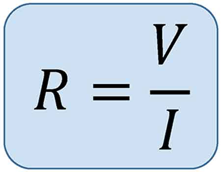
The resistance formula, R = V/I, shows how voltage and current determine opposition in a circuit. Central to Ohm’s Law, it is widely applied in electronics, power distribution, and engineering to calculate resistance, ensure efficiency, and design reliable electrical systems.


What is a Resistance Formula?

The resistance formula is a vital tool in understanding and optimizing electrical circuits. By analyzing the interplay between Ohm's law, conductor material, wire length, cross-sectional area, and temperature, we can manipulate Resistance to improve circuit performance. Balancing these factors ensures the efficient flow of electrons, minimizes energy loss, and maximizes the effectiveness of our electrical devices.

✅ R = V/I links voltage, current, and resistance

✅ Essential for circuit analysis and design

✅ Applied in electronics, power systems, and physics


Electrical circuits are essential for powering our daily lives, and understanding the factors that influence their performance is key to optimizing their efficiency. A critical aspect of electrical circuits is the Resistance they encounter, which directly affects the flow of electrons. Based on Ohm's law, the formula helps us analyze and manipulate various elements within a circuit. Topics like electrical resistance and the unit of electrical resistance expand on how opposition to current flow is measured and applied in engineering.

The flow of charge in any conductor depends on material properties and circuit design, where individual resistances combine differently depending on series or parallel circuit arrangements. According to law resistance principles, the total parallel resistance is always less than the smallest branch, and values are measured as resistance in ohms. Materials with the smallest resistivities like copper conduct efficiently, though their performance is affected by the temperature coefficient of resistivity, which alters conduction as heat rises. For visual examples and diagrams, resources such as Wikimedia Commons provide helpful illustrations.


Ohm's Law

Ohm's law is fundamental to understanding electrical circuits. It states that the Voltage across a conductor is directly proportional to the electric Current passing through it, and the constant of proportionality is the electrical Resistance. In mathematical terms, Ohm's law can be expressed as V = IR, where V is the Voltage, I is the electric Current, and R is the Resistance. Related principles, including Ampere’s Law and the Biot-Savart Law, further explain how current and magnetic fields interact with resistance in circuits.

The formula R = ρ(L/A) is derived from Ohm's law and describes how R depends on the conductor's material, length (L), and cross-sectional area (A). The resistivity (ρ) is a property unique to the conductor material and represents its ability to impede the flow of electrons. Different materials, such as copper or aluminum, have different resistivities, affecting the overall electrical R.

Wire length and cross-sectional area play a significant role in determining a conductor's R. As the wire length increases, so does the R, as electrons face more obstacles. Conversely, increasing the cross-sectional area reduces R, allowing more electrons to flow through the conductor simultaneously. This inverse relationship between R and cross-sectional area is vital in designing circuits to minimize energy loss and optimize efficiency.


Various factors influence the resistivity of conductor material. For instance, impurities in the material can hinder electron flow, thereby increasing resistivity. Additionally, the arrangement of atoms within the material's lattice structure affects the ease with which electrons can pass. Finally, the temperature coefficient is crucial, as fluctuations can alter resistivity. Generally, R increases with higher temperatures as atoms vibrate more and impede electron flow.

Resistance and conductance differ in their relationship to the flow of electrons. While R quantifies the opposition a conductor presents to the flow of electrons, conductance represents the ease with which electrons can pass. Mathematically, conductance (G) is the reciprocal of Resistance (R), and is measured in Siemens (S):

G = 1/R

The formula can be used to calculate power dissipation in a circuit. Power (P) is the product of Voltage (V) and current (I): P = VI. Using Ohm's law, we can substitute V = IR into the power formula to obtain P = I^2R. This equation demonstrates that higher R results in greater power dissipation, manifesting as heat. Hence, managing R is essential in preventing energy loss and maintaining circuit efficiency.

Ohm's law defines a mathematical relationship involving V, R, and current (I) within an electrical component. Ohm, denoted by the Greek letter omega (Ω), is the unit of measurement for R. Furthermore, Ohm's law can derive a power equation by computing electrical power, quantified in watts. Subsequently, Gustav Kirchhoff built upon Ohm's foundational work and introduced Kirchhoff's rules, two equalities addressing current and Voltage in an electric circuit model.

Ohm's law outlines the fundamental principles of electrical circuits, highlighting the interdependence between voltage, current, and resistance. This relationship can be expressed in three different formulas:

V = I × R (Voltage equals Current multiplied by Resistance)
R = V / I (Resistance equals Voltage divided by Current)
I = V / R (Current equals Voltage divided by Resistance)

These formulas illustrate the interconnection of voltage, current, and resistance in electrical circuits. By manipulating these relationships, we can analyze the behaviour of circuits, troubleshoot issues, and optimize efficiency.

The significance of Ohm's law extends beyond its mathematical representation. It forms the basis for understanding various electrical phenomena, including power dissipation, energy consumption, and the impact of R on the performance of electrical components. The role of resistance is closely tied to capacitance and inductance, which determine energy storage and reactance in alternating current systems.

As we explore the vast applications of electrical circuits, understanding the formula allows us to make informed decisions in choosing conductor materials, adjusting wire length and cross-sectional area, and considering temperature fluctuations. With an understanding of how these factors interact, we can continue to innovate, create, and harness the power of electricity to achieve a brighter future.


Related Articles


View more

Sign Up for Electricity Forum’s Newsletter

Stay informed with our FREE Newsletter — get the latest news, breakthrough technologies, and expert insights, delivered straight to your inbox.

Electricity Today T&D Magazine Subscribe for FREE

Stay informed with the latest T&D policies and technologies.
  • Timely insights from industry experts
  • Practical solutions T&D engineers
  • Free access to every issue

Live Online & In-person Group Training

Advantages To Instructor-Led Training – Instructor-Led Course, Customized Training, Multiple Locations, Economical, CEU Credits, Course Discounts.

Request For Quotation

Whether you would prefer Live Online or In-Person instruction, our electrical training courses can be tailored to meet your company's specific requirements and delivered to your employees in one location or at various locations.