Green Electricity


Green Electricity

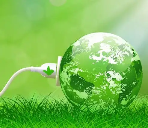
Green electricity integrates renewable energy sources such as solar PV, wind turbines, and hydropower into smart grids, improving power quality, decarbonization, efficiency, and reliability for industrial loads and utility-scale networks.


What is green electricity?

Green electricity is renewable-source power via smart grids to cut emissions and enhance system efficiency.

✅ Integrates PV, wind, hydro with power electronics and converters

✅ Enhances grid stability via inverters, FACTS, and smart protection

✅ Reduces CO2, improves efficiency, supports microgrids and storage


Green electricity is a term describing what is thought to be environmentally friendly sources of electricity. Typically, this refers to renewable and non-polluting energy power sources. For a broader perspective on how different technologies contribute, see this overview of sources of electricity across modern grids.

Green electricity includes natural energetic processes which can be harnessed with little pollution. Anaerobic digestion, geothermal power, wind power, small-scale hydropower, solar power, biomass power, tidal power and wave power fall under such a category. Some versions may also include power derived from the incineration of waste. Comparisons with other clean options are summarized in this guide to alternative electricity solutions used worldwide.


Energies Wind Electricity 
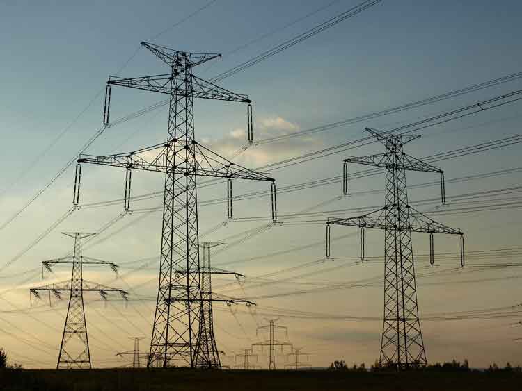
The winds that blow across the UK can be harnessed by turbines to provide Green electricity. Wind turbines sited in suitable locations already provide a small, but growing percentage of the UK's electricity, and are used successfully all around the world. In fact wind power is the world's fastest growing energy source! Wind turbine technology has greatly improved over the last ten years, making wind turbines quieter and more efficient so that electricity generated from the wind is now often competitive with traditional coal-fired and nuclear power stations. Wind turbines are also beginning to be built at sea — in the future much of our electricity could come from these offshore windfarms. Understanding how turbines integrate into national systems is covered in this primer on electricity generation methods and planning.


Solar Electricity
Many people believe that we don't get much solar Green electricity here in the UK. In fact solar power is already being used to provide essential power for many types of equipment being used in both remote and urban areas across the country. A solar photovoltaic (PV) module works by converting sunlight directly into electricity (even on cloudy days) using semiconductor technology. The vast majority of solar modules available today use "waste" silicon from the computer chip industry as the semiconductor material. They can be integrated into buildings and even made into roof tiles virtually indistinguishable from normal tiles. 
Solar Electricity can also be used to heat water directly using specially designed collectors. Even in winter a useful amount of hot water can be produced from roof top collectors. A third way to use solar energy is simply to design buildings to make maximum use of the sun. Using this so-called 'passive solar' approach, much of the energy that we currently use for heating, lighting and air conditioning can be saved. Homeowners can explore practical steps to generate electricity with rooftop PV and storage.


Hydro Electricity
Water turbines have been used to provide Green electricity for over 100 years and presently provide over 1% of the UK's electricity. Although most of the possible sites for large hydropower stations in the UK have already been developed, there is a large potential for smaller schemes. These can either use a small dam or work as a 'run of the river' system which has a minimal impact on the local environment. Design considerations for small schemes are outlined in this resource on water electricity systems for communities.


Wave Electricity
Many different devices have been designed over the years to try and capture some of this huge energy resource — the latest one has recently started generating Green electricity on the isle of Islay, off the West Coast of Scotland. In this machine waves hitting the shore are channelled into a large tube to power a specially designed turbine. With the proper support, wave power could provide a significant proportion of the UK's electricity needs in the future.


Tidal Electricity
Tidal power has been used in Britain for over a thousand years — at the time of the Doomsday book over 5,000 tide powered mills were recorded. Unlike other Green electricity renewable energy sources, which depend on the weather, tidal power is as predictable as the tides themselves. One way to capture tidal energy is to build a barrage across an estuary, storing water behind it as the tide rises and then releasing the stored water through turbines at low tide. Several sites around the UK could be suitable for this type of tidal system, the largest being the Severn Estuary. Another way is to use 'marine current turbines', which work like underwater wind turbines, harnessing tidal currents instead of the winds.


Geothermal Electricity
Geothermal energy comes from hot rocks deep underground. In some parts of the world steam comes to the surface and can be used to run steam turbines to produce Green electricity directly. In other places water can be pumped down and heated by the rocks to make steam. Geothermal energy can also be used to provide hot water and heating for buildings. Case studies of enhanced systems are available in this overview of geothermal electricity projects worldwide.


Biomass Electricity
Either agricultural wastes or specially grown plants can be used as a fuel to run small Green electricity power stations. As plants grow they absorb carbon dioxide (the main gas responsible for climate change) which is then released when the plants are burnt. So using biomass does not add any extra carbon dioxide into the atmosphere. Specially grown 'energy crops' provide not only an environmentally sound source of electricity, but also an important new opportunity for farmers. Analyses of supply chains and grid impacts appear in this review of electricity production from biomass and other renewables.


Landfill gas Converted to Electricity
As rubbish decomposes in the landfill sites where our household waste is dumped, it gives off methane gas. This gas can be captured and burnt in a gas turbine to produce an attractive Green electricity tariff. Burning the gas does give off carbon dioxide but since methane, which is emitted from the landfill site, is in fact a much more powerful greenhouse gas it is better to burn it than to allow the methane to escape into the atmosphere. There are already many landfill gas systems operating in the UK.


Waste Incineration Electricity
The UK generates an enormous amount of waste, and space at landfill sites is quickly running out. The best solution would be to recycle as much of the waste as possible, but instead incinerators are being constructed to burn the waste. In some cases the energy is being used to generate green electricity. However many environmentalists are still concerned about the emission of harmful dioxins and also about the loss of a valuable resources that could have been recycled. You can read about Greenpeace's views on incineration.


Related Articles

Related News

Definition of a Rectifier

Definition of a rectifier explains AC to DC conversion using diodes, bridge or full-wave circuits, filters, and regulators to supply stable DC, reduce ripple, and power electronics, chargers, and DC motor drives.


What Is the Definition of a Rectifier?

An explanation of devices that convert AC to DC using diodes and filtering to deliver regulated, low-ripple DC power.

✅ Converts alternating current to direct current via diodes

✅ Topologies: half-wave, full-wave, bridge rectifier

✅ Uses filters and regulators to minimize ripple and stabilize DC


Understanding the definition of a rectifier is fundamental to grasping the complexities of power electronics and electrical engineering. Rectifiers are pivotal in converting AC power to DC power, a critical process for operating numerous electronic devices. By delving into the intricacies of half-wave, full-wave, and bridge rectifiers, as well as the silicon-controlled rectifier, it becomes clear that these devices are crucial in shaping the modern world of electronics. For readers new to the basics, an overview of the difference between AC and DC can clarify foundational concepts.


In electrical engineering, the definition encompasses a vital device that plays a crucial role in converting alternating current (AC) into direct current (DC). It  is an essential component in power electronics. It facilitates the conversion of AC power, commonly used in households and businesses, to DC power that electronic devices rely on. To contextualize this conversion, understanding alternating current behavior in typical distribution systems explains the need for rectification.

They come in various forms, such as diodes, mercury arc valves, and silicon-controlled rectifiers (SCRs). A diode, the most basic rectifying component, allows current to flow in only one direction. This feature helps convert AC power, which alternates direction, to DC power that flows in a single, continuous direction. For measurement and notation conventions, see how DC current is defined and applied in circuit analysis.

AC to DC conversion regulates voltage to create a steady and reliable energy supply. Throughout this conversion, rectifiers often assume different configurations depending on the specific application or requirement. Two popular configurations are the half-wave rectifier and the full-wave rectifier. Downstream stabilization is often handled by a voltage regulator that smooths residual ripple and safeguards loads.

A half-wave type allows only one half of the AC waveform to pass through while blocking the other half. This type is relatively simple and cost-effective but has a few downsides, such as lower efficiency and increased ripple voltage. Ripple voltage refers to the residual periodic variation of the DC output voltage. The result is an unsteady DC output, which might be undesirable in certain applications.

On the other hand, the full-wave type allows both halves of the AC waveform to pass through, effectively doubling the output frequency and reducing the ripple voltage. This configuration improves efficiency and provides a smoother, more consistent DC output voltage. The full-wave type has two primary forms: the center-tap configuration and the bridge rectifier.

The bridge rectifier is a highly efficient configuration that uses four diodes in a specific arrangement. This configuration eliminates the need for a center-tapped transformer, a key component in center-tap full-wave rectifiers, thus reducing overall size and cost. In addition, the bridge rectifier provides better voltage regulation and reduced harmonic distortion, making it ideal for various applications. For consistent terminology across datasheets, reviewing key electricity terms can prevent misinterpretation during design.

They serve numerous purposes in various fields. For instance, they are used in power supply circuits of electronic devices, battery chargers, and welding equipment. In addition, they help in voltage regulation for DC power supplies and extract radio signals from transmitted modulated signals. Many of these uses depend on stable direct current characteristics to ensure predictable device behavior.

Silicon-controlled rectifiers (SCRs) represent a more advanced type of rectifier. As silicon-based semiconductor switches, SCRs can control large amounts of current with a small input signal. This ability to manage current flow in a controlled manner sets SCRs apart from regular rectifiers, like diodes. As a result, SCRs are often used in power control applications, such as motor speed controllers, light dimmers, and temperature regulators.

Understanding how rectifiers play a pivotal role in industries and everyday applications is essential. One such application is in electric vehicles (EVs), where rectifiers contribute to charging systems by converting AC power from the grid to DC power for charging the battery. Additionally, they are utilized in renewable energy systems, like solar power and wind power, to convert the harvested energy into a stable and usable form for various applications. At a broader level, a concise electricity definition helps frame how conversion stages integrate with generation, storage, and loads.

Another application is in telecommunications equipment, where they help maintain a continuous and stable power supply. In the aviation and marine industries, rectifiers ensure sensitive equipment operates with minimal interference from fluctuating power sources. Moreover, they are employed in power supply units of medical devices, computers, and other critical equipment that demand stable power supplies.


How does it work in AC to DC conversion?

Its primary function is to convert AC voltage, which periodically reverses direction, into DC voltage, which flows in one direction. Its simplest form it consists of a diode, which allows current to pass in only one direction. When connected to an AC power source, the diode rectifies the current by blocking the negative half-cycles of the AC waveform. More advanced configurations, like full-wave rectifiers and bridge rectifiers, rectify both the positive and negative half-cycles, increasing efficiency and providing a smoother output.


What are the differences between half-wave and full-wave rectifiers?

The key difference between half-wave and full-wave rectifiers lies in their efficiency and output. A half-wave type only allows one-half of the AC waveform to pass through, blocking the other half. As a result, it has lower efficiency, increased ripple voltage, and produces an unsteady DC output.

On the other hand, a full-wave type allows both halves of the AC waveform to pass through, leading to increased efficiency and reduced ripple voltage. In addition, the full-wave type produces a smoother, more consistent DC output voltage, making it more suitable for applications that require a stable power supply. The full-wave type can be implemented using a center-tap or bridge rectifier configuration.


Related Articles

View more

Electricity Cost Principles Explained

Electricity cost reflects kWh rates, tariffs, demand charges, power factor penalties, and TOU peak/off-peak pricing, driven by load profiles, utility billing, transmission and distribution fees, and efficiency measures in industrial, commercial, and residential systems.


What Is Electricity Cost?

Electricity cost is the total price per kWh including energy, demand, and network charges under applicable tariffs.

✅ Includes energy (kWh), demand (kW), and fixed charges

✅ Varies by TOU tariffs, peak/off-peak, and seasons

✅ Affected by power factor, load profile, and efficiency


Electricity Cost principles involve looking at how much electricity consumption and we have to understand how it's measured.

At its core, understanding power use starts with grasping what electricity is and how it behaves in circuits.

It is determined at any moment and is measured in watts consumed. For example: if you want to determine the bill energy or bill electricity rate: For a refresher, see what a watt represents to relate device ratings to instantaneous power.

  • A 100-watt light bulb uses 100 watts.
  • A typical desktop computer uses 65 watts.
  • A central air conditioner uses about 3500 watts.

These device ratings illustrate electric load in practical terms as each appliance contributes to total demand.

If you want to know how to rate electricity pricing, you want to know how much energy you're using. When you use 1000 watts for an hour, that's a kilowatt-hour. For example:

  • Ten 100-watt light bulbs on for an hour, is 1 kWh
  • Ten 100-watt light bulbs on for 1/2 an hour, is 0.5 kWh
  • Ten 50-watt light bulbs on for an hour, is 0.5 kWh
  • One 60-watt light bulb on for an hour, is 0.06 kWh (60/1000)
  • Running a 3500-watt air conditioner for an hour is 3.5 kWh.

The average U.S. household used 10,654 kWh a year in 2001, or 888 kWh/mo. (Dept. of Energy) The U.S. as a whole used 3,883 billion kWh in 2003, or 13,868 kwH per person based on a population of 300 million. (Dept. of Energy)


Watt-hours

For smaller items we use the term watt-hours instead of kilowatt-hours. For example, we say a 60-watt light bulb uses 60 watt-hours of electricity billed, not 0.060 kWh. If you're unsure, this overview of what a watt-hour means clarifies the relationship between power and time.

Note that the "-hours" part is important. Without it we'd have no idea what period of time we were talking about.

If you ever see a reference without the amount of time specified, it's almost certainly per hour.

If your device lists amps instead of watts, then just multiply the amps times the voltage to get the watts. For example:

2.5 amps x 120 volts = 300 watts

Trivia: On a peak day in 2009, California used 50,743 megawatt-hours of electricity, or 50,743,000,000 watt-hours.

How much does electricity cost?


Electricity Cost

It depends on where you live (like Ontario), how much you use, and possibly when you use it. There are also fixed charges that you pay every month no matter how much electricity you use. For example, I pay $6/mo. for the privilege of being a customer of the electric company, no matter how much energy I use. Local infrastructure and electricity supply conditions can also influence pricing tiers.

Check your utility bill for the rates in your area. If it's not on your bill then look it up on the utility's website. National summaries of electricity prices help you compare trends across regions.

The electric company measures how much electricity you use in kilowatt-hours. The abbreviation for killowatt-hour is kWh. Note that on your bill there can be multiple charges per kWh (e.g., one for the "base rate", another for "fuel") and you have to add them all up to get the total cost per kWh. This measurement is recorded by a watt-hour meter that cumulatively tracks energy over time.

Most utility companies charge a higher rate when you use more than a certain amount of energy, and they also charge more during summer months when electric use is higher. As an example, here are the residential rates prices electricity for Austin, Texas (as of 11-03):

First 500 kilowatts5.8¢ per kilowatt hour (kWh)

Additional kilowatts (May-Oct.)10¢ per kilowatt hour

Additonal kilowatts (Nov.-Apr.)8.3¢ per kilowatt hour

These figures include a fuel charge of 2.265¢ per kWh.

The average cost of residential electricity was 9.86¢/kWh in the U.S. in March 2006. The average household used 888 kWh/mo. in 2001 and would pay $87.56 for it based on the March 2006 average rate. (Dept. of Energy)

The cost of electricity varies by region. In 2003 the price ranged from 5.81¢ in Tennessee to 12¢ in California, 14.314¢ in New York, and 16.734¢ in Hawaii. In Summer 2001, electricity was a whopping 20¢/kWh in parts of California.


Related Articles

View more

Electricity Generation Power Production

Electricity generation is the process of producing electric power from various energy sources, including fossil fuels, solar, wind, hydro, and nuclear. It uses turbines and generators to convert mechanical or thermal energy into electrical energy for residential, commercial, and industrial use.


What is Electricity Generation?

Electricity generation is a process that involves producing electrical power from various sources.

✅ Converts mechanical, thermal, or chemical energy into electrical power

✅ Uses generators powered by steam, wind, water, or combustion

✅ Essential for powering homes, industries, and transportation


In the United States, power production from utility-scale generators was about 4.1 trillion kilowatt-hours (kWh) in 2019. Fossil fuels, including coal, natural gas, and petroleum, produced about 63% of the electricity, while nuclear energy produced around 20%. The remaining 17% was generated from renewable energy sources, including solar photovoltaics, wind turbines, and hydroelectric power production. To explore the full process from fuel to flow, see our detailed guide on how electricity is generated.


Electricity Generation Sources Compared

Energy Source How It Generates Electricity Global Usage (approx.) Carbon Emissions Renewable?
Coal Burns to heat water → steam → turbine spins generator 35% High No
Natural Gas Combusts to drive turbines directly or via steam 23% Moderate No
Nuclear Nuclear fission heats water → steam → turbine 10% Low No (but low-carbon)
Hydropower Flowing water spins turbines 15% Very Low Yes
Wind Wind turns large blades connected to a generator 7% Zero Yes
Solar PV Converts sunlight directly into electricity via photovoltaic cells 5% Zero Yes
Geothermal Uses Earth’s internal heat to create steam and turn turbines <1% Very Low Yes
Biomass Burns organic material to generate heat for steam turbines ~1.5% Moderate (depends on fuel) Partially


Hydroelectric Power Generation

Hydroelectric power production units utilize flowing water to spin a turbine connected to a generator. Falling water systems accumulate water in reservoirs created by dams, which then release it through conduits to apply pressure against the turbine blades, driving the generator. In a run-of-the-river system, the force of the river current applies pressure to the turbine blades to produce power. In 2000, hydroelectric generation accounted for the fourth-largest share (7 percent) of electricity production, at 273 billion kWh. Explore how water and electricity interact in hydroelectric plants, where falling water is converted into renewable energy.


Non-Hydro Renewable Energy Sources in Electricity Generation

Non-water renewable sources, including geothermal, refuse, waste heat, waste steam, solar thermal power plants, wind, and wood, contribute only small amounts (about 2 percent) to total power production. In 2019, power production from these sources totalled 84 billion kWh. The entire electric power industry production in 2019 was 3,800 billion kWh, with utilities' net production accounting for 3,015 billion kWh and net generation by non-utility power producers 785 billion kWh.


U.S. Electricity Generation by Energy Source: Trends and Shifts

The United States' share of electrical energy production from different sources has changed more rapidly since 2007 than ever since 1950. On the other hand, Canada's energy production is significantly less than that of the USA, primarily in Ontario and British Columbia. At least three trends are catalyzing these changes: (1) the low price of natural gas; (2) the rise in renewable and distributed generation due to falling costs; and (3) recent Federal and State policies impacting production. There are many innovative ways to generate electricity, from traditional fossil fuels to cutting-edge renewable technologies.


Fuel Source Diversity in U.S. and Canadian Electricity Production

Diversity is a key attribute in U.S. and Canadian electricity production. However, rather than being the result of a deliberative, long-term national initiative, this diversity has developed through spurts of growth in specific production technologies at different times. This is often due to policies, historical events, capital costs, fuel costs, and technological advancements.


Historical Growth of Electricity Generation by Energy Source

Most energy sources have experienced eras of significant capacity growth in terms of terawatt hours: hydro (1930‒1950, not shown); coal (1950-1985); nuclear (1960‒1980); natural gas (1990‒2010); and renewables (2005‒present). Nuclear energy is increasingly recognized as a key solution for achieving carbon reduction goals—learn how it contributes to net-zero emissions.


Changing U.S. Power Generation Mix: Centralized to Distributed Energy

The U.S. generation mix has undergone significant changes over the past few decades and is projected to continue evolving substantially. The U.S. generation fleet is transitioning from one dominated by centralized generators with high inertia and dispatchability to one more hybridized, relying on a mixture of traditional, centralized production and variable utility-scale and distributed renewable energy production.


Power Generation Technologies: From Diesel Engines to Wind Turbines

To generate power, various sources are utilized, including diesel engines, gas turbines, and nuclear power plants. Fossil fuels, including natural gas and coal, are burned to create hot gases that go through turbines, which spin the copper armature inside the generator and generate an electric current. In a nuclear power plant, nuclear reactions generate heat that is used to heat water, which then turns into steam and passes through a turbine to produce electricity. In a wind turbine, the wind pushes against the turbine blades, causing the rotor to spin and generating an electric current. In a hydroelectric turbine, flowing or falling water pushes against the turbine blades, causing the rotor to spin and generating an electric current. As the global energy landscape evolves, many experts are re-evaluating the role of nuclear power—learn more in our feature on the future of nuclear energy.


Electricity Generation by Utilities and Non-Utility Power Producers

To meet these immediate demands, utilities and nonutility power producers operate several electric generating units powered by various fuel sources. Renewable fuels, such as water, geothermal, wind, and other renewable energy sources like solar photovoltaics, are used as sources of power, alongside fossil fuels and uranium.


motor


diagram


Fossil Fuel Electricity Generation: Coal, Natural Gas, and Petroleum

Coal was the fuel used to generate the largest share (51.8 percent) of electricity in 2000, with natural gas and petroleum accounting for 16.1 percent and 3 percent, respectively. Steam-electric generating units burn fossil fuels, such as coal, natural gas, and petroleum, to produce steam. This steam is then used to turn a turbine into a generator, producing power. On the other hand, gas turbine generators burn fuels to create hot gases, which also go through a turbine, spinning the copper armature inside the generator and generating an electric current. Diesel engine generators are also used, where the combustion occurs inside the engine's cylinders, which are connected to the generator's shaft. The mechanical energy provided by the turbine drives the generator, which in turn produces energy.


Electricity Generation Trends and the Global Shift Toward Renewables

The production of electrical energy has experienced various eras of significant capacity growth in the United States, Canada, and other countries worldwide. The future of power production is transitioning to a more hybridized generation fleet that relies on a combination of traditional, centralized power production and variable utility-scale and distributed renewable energy sources. Low natural gas prices drive this transition, the rise of renewable and distributed energy sources, and recent Federal and State policies that impact generation. Discover the most common renewable energy sources powering the shift toward a cleaner, more sustainable electricity future.


Enhance your expertise in clean energy with our comprehensive Renewable Energy Grid Integration Training course. Designed for electrical professionals, this course covers the challenges and solutions associated with connecting solar, wind, and other renewable energy sources to the power grid. Stay ahead of industry trends, improve system reliability, and gain valuable skills to support the transition to a sustainable energy future. Enroll today and take the next step in your professional development.


Frequently Asked Questions

How is electricity generated from renewable energy sources?

Electricity is generated from renewable energy sources by converting the energy of the sun, wind, water, or earth into electrical energy. For example, solar photovoltaic panels generate power directly from sunlight, wind turbines to generate electricity from wind energy, and hydroelectric power plants generate power from falling water.


What are the different types of fossil fuels used?

The different types of fossil fuels used include coal, natural gas, and petroleum. Coal is the most commonly used fossil fuel for energy production, followed by natural gas and oil.


What are the advantages and disadvantages of using nuclear power plants for electricity generation?

Advantages of using nuclear power plants include that they produce a large amount of energy with a low amount of fuel, emit less carbon dioxide than fossil fuel power plants, and are not dependent on weather conditions like wind or solar power. Disadvantages include the risks associated with nuclear accidents, the high cost of building and maintaining nuclear power plants, and the long-term storage of nuclear waste.


How do gas turbines work to generate electricity?

Gas turbines burn natural gas or other fuels to heat air, which expands and drives the turbine. Finally, the turbine is connected to a generator that converts the mechanical energy of the turbine into electrical energy.


What is the role of steam turbines in electricity generation?

Steam turbines are commonly used to convert thermal energy from steam into mechanical energy that drives a generator. Steam is produced by burning fossil fuels or using heat from nuclear reactions or geothermal sources. The steam drives the turbine blades, which are connected to the generator to produce electricity.


What are some examples of non-renewable energy sources?

Examples of non-renewable energy sources used for power production include fossil fuels, such as coal, natural gas, and petroleum, as well as nuclear energy.


How is electricity generated and distributed in the United States?

Various power plants, including those powered by fossil fuels, nuclear energy, and renewable energy sources, generate electricity in the United States. Electric power is transported over a complex network of power lines and transformers to homes, businesses, and other consumers through local utility companies. The Federal Energy Regulatory Commission (FERC) and various state regulatory agencies regulate power distribution.


Related Articles


View more

Home Electricity - Electrical Energy Information

Home electricity powers lighting, appliances, and electronics using energy from the grid or renewable sources like solar. Understanding usage, safety, and efficiency helps reduce costs and improve performance in daily life.


What is Home Electricity?

Home electricity refers to the power used to operate household systems and devices.

✅ Powers lights, appliances, HVAC, and electronics

✅ Supplied by utilities or solar energy systems

✅ Measured in kilowatt-hours and billed monthly


How Electricity Enters and Flows Through Your Home

Electricity originates from a distant power station, fueled by coal, natural gas, nuclear power, or renewable sources, and is transformed into high-voltage energy for long-distance transmission. Along the way, transformers step this voltage down to safe, usable levels. When it reaches your home, the electricity flows through a service line to a main panel, where circuit breakers distribute it to branch circuits that power every room and outlet.

In the United States, most residential circuits provide about 120 volts of alternating current (AC) at 60 Hz. Voltage measures the energy per unit charge: 120 volts means 120 joules of energy are transported by each coulomb of charge. One coulomb per second equals one ampere, so an appliance drawing 1 ampere at 120 volts consumes energy at 120 watts—120 joules per second.


How Appliances Use Electrical Energy

When you switch on an appliance, it allows 120 volts of potential to push current through the device—similar to using water pressure to move water through a pipe. As electric charge flows, energy is transformed into useful work like heating, lighting, or mechanical motion. Voltage gradually drops to nearly zero by the time the current exits the appliance.

This “spent” charge is carried back to your electrical panel via the neutral wire and ultimately to the ground through the grounding system. The ground serves as a vast reservoir, stabilizing voltages and protecting users in the event of a fault.


Understanding Home Wiring and Safety

In a standard polarized receptacle, the smaller prong connects to the hot wire (120 volts), and the wider prong to the neutral (0 volts). The hot wire delivers the current; the neutral completes the circuit back to the panel. A separate ground wire exists for safety—it’s not part of the working circuit but protects against electric shock if a fault occurs.

Most wall outlets contain two receptacles (a duplex) wired in parallel. This means two appliances plugged in will receive the same 120-volt supply but can draw different amounts of current. Parallel wiring is standard throughout the home, allowing consistent voltage distribution while accommodating various electrical loads.


Where the Energy Comes From and Where It Goes

Electricity used at home ultimately comes from generators that elevate the voltage of electric charge before it travels across the grid. After powering your home, the now low-energy charge returns to the ground. This closed-loop system—from the earth to the generator and back—enables efficient energy use and the safe disposal of spent charge.

Whether your electricity comes from traditional utilities or rooftop solar panels, the underlying principles remain the same: raise voltage at the source, deliver it efficiently, use it safely, and return it to ground. Understanding these concepts helps homeowners stay informed, reduce waste, and use electricity more safely and effectively.


Related Articles


View more

What is Medium Voltage iExplained

Medium voltage refers to electrical systems operating between 1 kV and 35 kV, used in industrial facilities, substations, and utility power distribution networks to safely transfer energy between low-voltage and high-voltage levels.


What is Medium Voltage?

Medium voltage refers to the electrical range between 1 kV and 35 kV, bridging the gap between low- and high-voltage systems for efficient energy transfer and safe power distribution across industrial, commercial, and utility applications.

✅ Used in substations, industrial plants, and utility grids

✅ Defined by IEEE and IEC classification standards

✅ Supports reliable energy transmission and electrical safety

A medium voltage (MV) system is crucial for distributing electricity in industrial, commercial, and institutional settings. It acts as the intermediary between high-voltage transmission lines and low-voltage consumer systems, ensuring efficient power delivery within a facility. This article provides a comprehensive overview of a medium voltage system, including its definition, applications, equipment, safety practices, and relevant standards. Understanding these concepts is vital for electrical professionals to ensure the safe and efficient operation of this critical power infrastructure. Medium voltage systems are essential links in 3 phase electricity networks, where balanced power delivery ensures efficient energy distribution across industrial and utility infrastructures.

Understanding medium voltage systems is essential for electrical professionals working in industrial, commercial, and institutional settings. This article provides a comprehensive overview of what constitutes medium voltage, its role in the power grid, common applications, and safety considerations. By grasping these key concepts, professionals can ensure the safe and efficient design, operation, and maintenance of these critical power systems. Understanding 3 phase power helps explain how medium voltage circuits maintain stable electrical loads in substations and manufacturing facilities.


Voltage Levels and Classifications

In the realm of electrical engineering, voltage levels are broadly categorized to distinguish their applications and safety requirements.  These categories range from LV, typically used for residential applications, to extra high voltage (HV) and ultra-high voltages employed in HV transmission across long distances. MV occupies a middle ground, generally falling between 1,000 volts (600 volts in some instances) and 35,000 volts (35 kV). This distinguishes it from HV used in transmission and lower voltages used in end-user applications. Many 3 phase transformers and pad-mounted transformer installations operate at medium voltage levels, stepping electrical energy down for safe use in local distribution systems.

To better visualize this, imagine electricity flowing like a river through the electrical grid. V is like the force propelling the water, and different levels represent different sections of the river. HV is like a powerful, fast-flowing river capable of transporting electricity over long distances. MV, on the other hand, is like a branching stream that distributes the water (electricity) to various destinations. It's the crucial link between the high-powered transmission lines and the LV systems that deliver power to individual consumers. For a foundational understanding, review basic electricity concepts that explain how V, current, and resistance interact within medium voltage electrical systems.


What is Medium Voltage Applications?

Medium voltage systems have a wide range of applications in industrial, commercial, and institutional settings. In industrial facilities, they power large motors, heavy machinery, and industrial processes. Commercial buildings utilize what is MV for HVAC systems, lighting, and other electrical loads. Institutions such as hospitals and universities rely on MV to support their critical operations.

The use of MV is increasing. Historically, it was mainly used for subtransmission and primary distribution, supplying distribution transformers that step down the voltage to LV for end-use equipment. It was also traditionally used in industries for MV motors. However, with advancements in power electronics and semiconductor technology, new applications are emerging, such as:

  • MV DC Distribution Grids: These grids offer higher efficiency in long-distance transmission and are being implemented in collector grids for wind and photovoltaic parks.

  • Renewable Energy Integration: MV systems play a vital role in integrating renewable energy sources into the power grid, enabling the transition to a more sustainable energy future.

The principles of active power apply directly to medium voltage operations, where real power flow efficiency determines the overall performance of industrial and commercial grids.


Frequently Asked Questions


How does MV differ from low and HV?

Medium voltage occupies a middle ground between LV, typically used for residential applications, and HV, employed for long-distance transmission. It's the "in-between" voltage level that allows us to efficiently distribute power to different consumers.


What is Medium Voltage Range ?

Generally, MV falls between 1,000 volts (600 volts in some instances) and 35,000 volts (35 kV). This range can vary slightly depending on regional standards and practices.  For example, ANSI standards in the US include voltages up to 69 kV in the MV class, while IEC standards use 1000 Vrms as the threshold between low and HV in AC installations.


What is MV in industrial, commercial, and institutional power systems?

Medium voltage is distributed within these facilities to power various equipment and loads. It's the primary level used within these settings before being stepped down to LV for end-use.


What are common applications of MV systems?

Common applications include powering large motors and machinery in industrial settings, as well as HVAC and lighting systems in commercial buildings, and critical operations in institutions such as hospitals.  Emerging applications include microgrids and the integration of renewable energy.


What are the key standards and regulations governing MV systems?

Key standards include those from ANSI, IEEE, and NEC, which provide guidelines for the design, installation, and safety of MV systems. These standards ensure that MV systems are implemented in a safe and consistent manner.

A Medium Voltage system is crucial for distributing electricity in industrial, commercial, and institutional settings. It acts as the intermediary between HV transmission lines and LV consumer systems, ensuring efficient power delivery within a facility. This article provides a comprehensive overview of a medium voltage system, including its definition, applications, equipment, safety practices, and relevant standards. Understanding these concepts is vital for electrical professionals to ensure the safe and efficient operation of this critical power infrastructure.


Related Articles


View more

Electricity and Magnetism - Power Explained

Electricity and magnetism are interconnected forces forming electromagnetism, which explains electric currents, magnetic fields, and their interactions. These principles power motors, generators, transformers, and more in modern electrical and magnetic systems.


What is: "Electricity and Magnetism"

Electricity and magnetism are fundamental forces in physics that form the basis of electromagnetism.

✅ Describe how electric charges and magnetic fields interact in nature and technology

✅ Underlie the function of motors, transformers, and generators

✅ Explain current flow, induction, and electromagnetic waves

Electricity - What is it?

Electricity is a form of energy that is transmitted through copper conductor wire to power the operation of electrical machines and devices, including industrial, commercial, institutional, and residential lighting, electric motors, electrical transformers, communications networks, home appliances, and electronics.

When charged particles flow through the conductor, we call it "current electricity". This is because when the charged particles flow through wires, electricity also flows. We know that current means the flow of anything in a particular direction. For example, the flow of water. Similarly, the flow of electricity in a specific direction is referred to as an electric current. The interplay of charge, field, and force is explored in what is electric load, covering how power is delivered in electromagnetic systems.

When an electric current flows, it produces a magnetic field, a concept closely tied to Faraday's Law of Induction, which underpins much of modern electrical engineering.


Magnetism  - What is it?

Magnetism is a type of attractive or repulsive force that acts up to certain distance at the speed of light. The distance up to which this attractive or repulsive force acts is called a "magnetic field". Magnetism is caused by the moving electric charges (especially electrons). When two magnetic materials are placed close to each other, they experience an attractive or repulsive force. To understand magnetic field strength and units, our magnetic induction basics in induction page discusses flux and Teslas.


What is the relationship between electricity and magnetism?

In the early days, scientists believed that there were two uniquely separate forces. However, James Clerk Maxwell proved that these two separate forces were actually interrelated.

In 1820, Hans Christian Ørsted observed a surprising phenomenon: when he switched on the battery from which the electric current was flowing, the compass needle moved away from the north pole. After this experiment, he concluded that the electric current flowing through the wire produces a magnetic field.

Electricity and magnetism are closely related to each other. The electric current flowing through the wire produces a circular magnetic field outside the wire. The direction (clockwise or counterclockwise) of this magnetic field depends on the direction of the electric current.

Similarly, a changing magnetic field generates an electric current in a wire or conductor. The relationship between them is called electromagnetism.

Electricity and magnetism are interesting aspects of electrical sciences. We are familiar with the phenomenon of static cling in our everyday lives - when two objects, such as a piece of Saran wrap and a wool sweater, are rubbed together, they cling.

One feature of this that we don't encounter too often is static "repulsion" - if each piece of Saran wrap is rubbed on the wool sweater, then the pieces of Saran wrap will repel when brought near each other. These phenomena are interpreted in terms of the objects acquiring an electric charge, which has the following features:

  • There are two types of charge, which by convention are labelled positive and negative.

  • Like charges repel, and unlike charges attract.

  • All objects may have a charge equal to an integral number of a basic unit of charge.

  • Charge is never created or destroyed.

To explore how electric and magnetic forces interact at a distance, see what is static electricityis, which includes examples like static cling and repulsion.


Electric Fields

A convenient concept for describing these electric current and magnetic current forces is that of electric field currents. Imagine that we have a fixed distribution of charges, such as on the plate below, and bring a test charge Q into the vicinity of this distribution.


img134 
 

Fig. 1 Test charge in the presence of a fixed charge distribution

This charge will experience a force due to the presence of the other charges. One defines the electric field of the charge distribution as:


img135

The electric field is a property of this fixed charge distribution; the force on a different charge Q' at the same point would be given by the product of the charge Q' and the same electric field. Note that the electric field at Q is always in the same direction as the electric force.

Because the force on a charge depends on the magnitude of the charges involved and the distances separating them, the electric field varies from point to point, both in magnitude and direction.

By convention, the direction of the electric field at a point is the direction of the force on a positive test charge placed at that point. An example of the electric field due to a positive point charge is given below. 


img136

Fig. 2: Electric field lines of a positive charge


Power and Magnetic Fields

A phenomenon apparently unrelated to power is electromagnetic fields. We are familiar with these forces through the interaction of compasses with the Earth's magnetic field, or the use of fridge magnets or magnets on children's toys. Magnetic forces are explained in terms very similar to those used for electric forces:

  • There are two types of magnetic poles, conventionally called North and South
  • Like poles repel, and opposite poles attract

However, this attraction differs from electric power in one important aspect:

  • Unlike electric charges, magnetic poles always occur in North-South pairs; there are no magnetic monopoles.

Later on we will see at the atomic level why this is so.

As in the case of electric charges, it is convenient to introduce the concept of a magnetic field in describing the action of magnetic forces. Magnetic field lines for a bar magnet are pictured below.

img137
 

Fig. 3: Magnetic field lines of a bar magnet

One can interpret these lines as indicating the direction that a compass needle will point if placed at that position.

The strength of magnetic fields is measured in units of Teslas (T). One tesla is actually a relatively strong field - the earth's magnetic field is of the order of 0.0001 T.


Magnetic Forces On Moving Charges

One basic feature is that, in the vicinity of a magnetic field, a moving charge will experience a force. Interestingly, the force on the charged particle is always perpendicular to the direction it is moving. Thus, magnetic forces cause charged particles to change their direction of motion, but they do not change the speed of the particle.

This property is utilized in high-energy particle accelerators to focus beams of particles, which ultimately collide with targets to produce new particles, including gamma rays and radio waves.

Another way to understand these forces of electricity and magnetism is to realize that if the force is perpendicular to the motion, then no work is done. Hence, these forces do no work on charged particles and cannot increase their kinetic energy.

If a charged particle moves through a constant magnetic field, its speed stays the same, but its direction is constantly changing. A device that utilizes this property is the mass spectrometer, which is used to identify elements. A basic mass spectrometer is pictured below.


img145
 

Figure 4: Mass spectrometer

In this device, a beam of charged particles (ions) enters a region of a magnetic field, where they experience a force and are bent in a circular path. The amount of bending depends on the mass (and charge) of the particle, and by measuring this amount one can infer the type of particle that is present by comparing it to the bending of known elements.


Magnet Power From Electric Power

A connection was discovered (accidentally) by Orsted over 100 years ago, when he noticed that a compass needle is deflected when brought into the vicinity of a current-carrying wire. Thus, currents induce magnetic fields in their vicinity. An electromagnet is simply a coil of wires which, when a current is passed through, generates a magnetic field, as below.


img149
 

Figure 5: Electromagnet

Another example is in an atom, where an electron is a charge that moves around the nucleus. In effect, it forms a current loop, and hence, a magnetic field may be associated with an individual atom. It is this basic property which is believed to be the origin of the magnetic properties of various types of materials found in nature.

Maxwell's equations (also known as Maxwell's theory) are a set of coupled partial differential equations that, together with the Lorentz force law, form the foundation of classical electromagnetism, which deals with electromagnetic radiation, electromagnetic waves, and electromagnetic force.  For a deeper understanding of the magnetic effects of electrical current, our article on electromagnetic induction explains how magnetic fields can generate electricity in conductors.


Related Articles


View more

Sign Up for Electricity Forum’s Newsletter

Stay informed with our FREE Newsletter — get the latest news, breakthrough technologies, and expert insights, delivered straight to your inbox.

Electricity Today T&D Magazine Subscribe for FREE

Stay informed with the latest T&D policies and technologies.
  • Timely insights from industry experts
  • Practical solutions T&D engineers
  • Free access to every issue

Download the 2025 Electrical Training Catalog

Explore 50+ live, expert-led electrical training courses –

  • Interactive
  • Flexible
  • CEU-cerified