Basic Electricity – Understanding Current, Voltage, Resistance, and Power
Basic electricity refers to the fundamental concepts of electric charge, current, voltage, and resistance. It explains how electric circuits work, how energy flows, and how components like wires, batteries, and switches interact in homes, schools, and industries.
What is Basic Electricity?
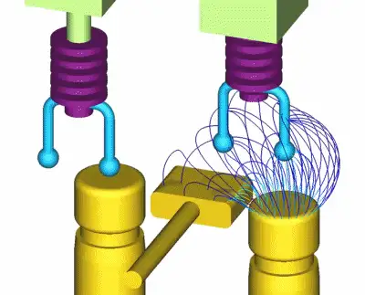
Basic electricity refers to the foundational principles that explain how electric energy is generated, transmitted, and used in circuits. When an electric current flows through a conductor, it creates a magnetic field (or “flux”) around it.
✅ Explains current, voltage, resistance, and power in simple terms
✅ Describes how electric circuits operate and transfer energy
✅ Essential for understanding household wiring, batteries, and switches
Understanding the fundamentals of voltage is essential for grasping how electric circuits function — see our full explanation of voltage.
The strength of this magnetic field increases when the conductor is shaped into a coil with multiple turns. In electrical engineering, this coiled conductor is known as an inductor. If a steady direct current (DC) flows through the coil, it forms an electromagnet—an object with magnetic properties that can be switched on and off using a basic electrical switch.
Basic Electrical Theory
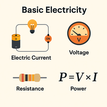
There are four basic electrical quantities that we need to know:
-
Current
-
Potential Difference (Voltage)
-
Power
-
Resistance
Electrical Current
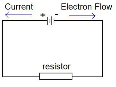
Current is the movement of electric charge through a conductor. Each electron carries a charge of 1.6 × 10⁻¹⁹ coulombs—too small to measure individually—so we measure charge in groups called coulombs. When 1 coulomb of charge passes through a point in a circuit per second, the current is 1 ampere (A). Electric current is measured in amperes and is essential to the functioning of all electrical systems. Learn how voltage drop affects electrical performance and safety in residential and industrial systems. You can estimate losses in long-distance wiring with our easy-to-use voltage drop calculator. For step-by-step guidance on circuit loss calculations, explore the voltage drop formula explained clearly.
Potential Difference
Voltage, or potential difference, refers to the energy per unit charge in a circuit. It represents the work each charge can perform. Think of voltage as the electrical pressure that pushes electrons through a conductor. Higher voltage means more potential energy available to do work, such as lighting a bulb or powering a motor.
Power in a Circuit
Electrical power is the rate at which energy is used or transferred in a circuit. It can be calculated using the formula:
Power (W) = Voltage (V) × Current (A)
This equation is fundamental in both residential and industrial applications, from estimating energy usage to designing electrical systems.
Electrical Resistant Behaviour
Resistance is the opposition to the flow of electric current. It determines how much current will flow for a given voltage. Materials like copper have low resistance and conduct electricity well, while materials like rubber have high resistance and are used as insulators. Learn how voltage drop affects electrical performance and safety in residential and industrial systems.
Electromagnetic Induction
There’s a reciprocal relationship between electric current and magnetism. When a magnet is moved past a conductor at a right angle, it induces a voltage in the conductor—a principle known as electromagnetic induction. The polarity of the induced voltage depends on the direction and orientation of the magnetic field.
This effect becomes more noticeable when the conductor is formed into a coil. As the north pole of the magnet passes the coil, voltage is induced, and current flows. When the south pole passes, the induced voltage reverses polarity, and the current changes direction. This principle is the foundation of generator operation. You can estimate losses in long-distance wiring with our easy-to-use voltage drop calculator.
The Generator and the Sine Wave
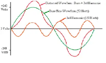
In an electric generator, coils placed on opposite sides of a rotating magnet generate alternating current (AC). These voltages combine, doubling the output. For example, a 120-volt, 60-Hz generator creates a wave that oscillates from +169.7V to -169.7V.
This wave is called a sine wave because the voltage at any point corresponds to the sine of the magnet’s angle of rotation. The cycle repeats 60 times per second in North America (60 Hz), creating the household AC power we are familiar with. For step-by-step guidance on circuit loss calculations, explore the voltage drop formula explained clearly.
Forms of Electricity: AC and DC
Electricity exists in two major forms:
-
Alternating Current (AC): The direction of current flow alternates regularly. AC electricity is used in power grids because it is easier to transmit over long distances and is compatible with devices such as transformers and capacitors.
-
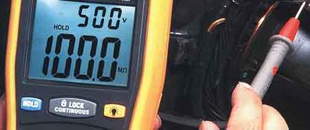
Direct Current (DC): The current flows steadily in one direction. DC is commonly used inside electronics and battery-powered devices. Unlike AC, the voltage remains constant, making it easy to measure with a DC voltmeter.
AC – Alternating Current
Alternating current is the most common form of electricity used in homes, businesses, and utilities. It alternates direction 50–60 times per second, depending on the region. AC is generated by AC generators and is favored for its ability to change voltage levels easily, making it efficient for transmission over long distances. Sudden dips in power can disrupt equipment — find out what causes voltage sag and how to prevent it.
DC – Direct Current
Direct current flows continuously in one direction. Because its voltage is steady or changes very slowly, it’s easy to measure. It is used in battery-powered systems and internal electronic circuits. Unlike AC, DC cannot be easily stepped up or down in voltage without the use of complex circuitry.
When calculating AC power, engineers use RMS (Root Mean Square) voltage, which gives an effective value comparable to DC. For example, 120V AC RMS is equivalent in power to 120V DC, despite the AC waveform's variations. Discover how water and electricity interact, including safety considerations and risks in common environments.
Transformers and Induction
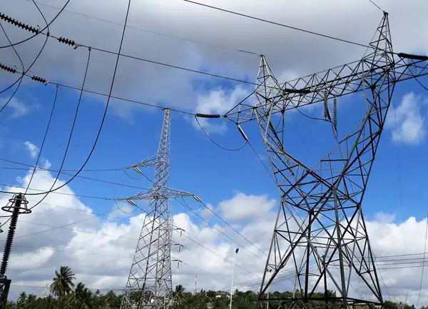
Transformers, built using coiled wires around iron cores, rely on electromagnetic induction. When AC flows through the primary coil, it creates a changing magnetic field that induces a voltage in the secondary coil. This allows voltage to be stepped up or down for different uses, such as high-voltage transmission or low-voltage device operation.
Atoms, Electrons, and Electric Charge
To fully grasp electricity, it’s essential to understand atomic structure. All matter is made up of atoms, which contain a nucleus of protons (positive) and neutrons (neutral), surrounded by orbiting electrons (negative). The outermost electrons—called valence electrons—can be knocked loose by energy, creating an electric current.
When electrons leave an atom, it becomes positively charged. This movement of charge is the essence of electricity. The ability of atoms to gain or lose electrons determines whether a material is a conductor (like copper) or an insulator (like plastic).
Electrical Charge and Attraction
One universal rule in electricity and magnetism is that like charges repel and opposite charges attract. A positively charged object will attract a negatively charged one. This principle governs everything from how circuits function to how magnetic fields interact with conductors. To understand how energy use is measured over time, read our overview of the watthour meter and its function.


