Electric Power Systems Explained
By R.W. Hurst, Editor
Electric power systems coordinate generation, transmission, and distribution using grids, substations, protection relays, and SCADA to maintain reliability, stability, power quality, efficient load flow, and renewable integration.
Overview: Electric Power Systems
Electric power systems form the backbone of modern society, quietly enabling everything from lighting and communications to industry, transportation, and healthcare. While often taken for granted, these systems are among the most complex engineered networks in existence. They must deliver power continuously, respond instantly to disturbances, and adapt to changing demand while meeting growing expectations for sustainability and resilience. Readers new to core concepts can review what electricity is to connect these technologies with fundamental principles.
At a high level, an electric power system brings together three tightly linked functions: producing electrical energy, moving it across long distances, and delivering it safely to end users. Electricity is generated from a mix of energy sources, including fossil fuels, nuclear power, and an expanding portfolio of renewable energy sources such as wind, solar, and hydro. Each source introduces different operating characteristics, costs, and control challenges. A broader overview of resource diversity can be found in our major sources of electricity article. Those interested in the conversion processes can explore how is electricity generated to understand key methods and tradeoffs.
Electric Power Production
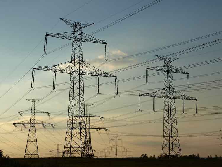
Once power is produced, it must be transmitted efficiently over high-voltage networks. Transmission systems reduce losses by operating at elevated voltages and interconnect large geographic regions to balance supply and demand. Substations play a critical role at this stage by transforming voltage levels, switching power flows, and isolating faults. As electrical energy moves closer to homes, businesses, and industrial facilities, distribution systems step down the voltage again and route power through increasingly dense local networks. For background on production metrics that storage helps smooth, consult electricity production data to see how output varies across time.
Modern Electric Power Systems Technologies
Modern electric power systems rely heavily on automation of T&D systems and monitoring to remain stable. Protection relays detect abnormal conditions such as short circuits or overloads and isolate affected equipment in fractions of a second. Supervisory control and data acquisition systems provide operators with real-time visibility into grid conditions, enabling informed decisions during normal operation and emergencies. For readers interested in how these elements fit into the broader network, the energy grid basics offer useful system-level context.
The growing share of renewable energy generation has reshaped how power systems are planned and operated. Wind and solar output vary with weather and time of day, which introduces uncertainty into system balancing. Energy storage technologies help address this challenge by absorbing excess generation and releasing it when demand rises. Batteries, pumped hydro, and flywheels are increasingly used to support frequency control, voltage regulation, and contingency response. A broader view of production scaling and plant types is provided in electricity generation overview that links equipment choices with system performance.
Microgrids
Microgrids have emerged as another important development. These smaller, localized systems can operate alongside the main grid or independently during outages. By combining local generation, storage, and advanced controls, microgrids enhance resilience for critical facilities and remote communities. They also reduce reliance on long transmission paths and can improve efficiency by placing generation closer to loads. For system-level context on grid architecture, the overview at electricity grid basics explains how modern networks coordinate supply and demand.
Grid Stability
Maintaining grid stability remains a central engineering challenge as systems grow more complex. Higher demand, aging infrastructure, and distributed generation all place additional stress on networks originally designed for one-way power flow. Engineers address these challenges using detailed studies, advanced controls, and coordinated protection schemes. Engineers use rigorous studies such as power system analysis to evaluate contingencies and design robust operating strategies.
Demand response has also become a practical operating resource. By using communication and pricing signals, utilities can encourage consumers to shift electric power use away from peak periods. This reduces strain on generation and transmission assets while improving overall system efficiency. These strategies are increasingly integrated into smart grid platforms that link customer behavior with system-level objectives.
Electric power systems also differ in how electricity is delivered to various load types. Single-phase supplies are common in residential settings, while three-phase power dominates commercial and industrial applications due to its efficiency and smoother power delivery. Ongoing innovation in transmission and distribution continues to focus on reducing losses, improving reliability, and supporting new technologies across the grid. A broader perspective on how generation scale and plant design influence system performance is provided in electrical energy generation overviews.
As electric power systems continue to evolve, their importance has only increased. The shift toward renewable generation, the need for resilient infrastructure, and the modernization of aging grids all place greater demands on how electrical energy is planned, controlled, and delivered. Reliable power now depends not only on physical equipment, but on coordinated system design, advanced controls, and informed operation that can adapt to a rapidly changing energy landscape.
Related Articles

