Resistance Formula Explained

By R.W. Hurst, Editor

resistance formula

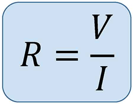
The resistance formula, R = V/I, shows how voltage and current determine opposition in a circuit. Central to Ohm’s Law, it is widely applied in electronics, power distribution, and engineering to calculate resistance, ensure efficiency, and design reliable electrical systems.


What is a Resistance Formula?

The resistance formula is a vital tool in understanding and optimizing electrical circuits. By analyzing the interplay between Ohm's law, conductor material, wire length, cross-sectional area, and temperature, we can manipulate Resistance to improve circuit performance. Balancing these factors ensures the efficient flow of electrons, minimizes energy loss, and maximizes the effectiveness of our electrical devices.

✅ R = V/I links voltage, current, and resistance

✅ Essential for circuit analysis and design

✅ Applied in electronics, power systems, and physics


Electrical circuits are essential for powering our daily lives, and understanding the factors that influence their performance is key to optimizing their efficiency. A critical aspect of electrical circuits is the Resistance they encounter, which directly affects the flow of electrons. Based on Ohm's law, the formula helps us analyze and manipulate various elements within a circuit. Topics like electrical resistance and the unit of electrical resistance expand on how opposition to current flow is measured and applied in engineering.

The flow of charge in any conductor depends on material properties and circuit design, where individual resistances combine differently depending on series or parallel circuit arrangements. According to law resistance principles, the total parallel resistance is always less than the smallest branch, and values are measured as resistance in ohms. Materials with the smallest resistivities like copper conduct efficiently, though their performance is affected by the temperature coefficient of resistivity, which alters conduction as heat rises. For visual examples and diagrams, resources such as Wikimedia Commons provide helpful illustrations.


Ohm's Law

Ohm's law is fundamental to understanding electrical circuits. It states that the Voltage across a conductor is directly proportional to the electric Current passing through it, and the constant of proportionality is the electrical Resistance. In mathematical terms, Ohm's law can be expressed as V = IR, where V is the Voltage, I is the electric Current, and R is the Resistance. Related principles, including Ampere’s Law and the Biot-Savart Law, further explain how current and magnetic fields interact with resistance in circuits.

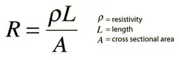
The formula R = ρ(L/A) is derived from Ohm's law and describes how R depends on the conductor's material, length (L), and cross-sectional area (A). The resistivity (ρ) is a property unique to the conductor material and represents its ability to impede the flow of electrons. Different materials, such as copper or aluminum, have different resistivities, affecting the overall electrical R.

Wire length and cross-sectional area play a significant role in determining a conductor's R. As the wire length increases, so does the R, as electrons face more obstacles. Conversely, increasing the cross-sectional area reduces R, allowing more electrons to flow through the conductor simultaneously. This inverse relationship between R and cross-sectional area is vital in designing circuits to minimize energy loss and optimize efficiency.
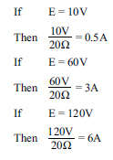
 

Various factors influence the resistivity of conductor material. For instance, impurities in the material can hinder electron flow, thereby increasing resistivity. Additionally, the arrangement of atoms within the material's lattice structure affects the ease with which electrons can pass. Finally, the temperature coefficient is crucial, as fluctuations can alter resistivity. Generally, R increases with higher temperatures as atoms vibrate more and impede electron flow.

Resistance and conductance differ in their relationship to the flow of electrons. While R quantifies the opposition a conductor presents to the flow of electrons, conductance represents the ease with which electrons can pass. Mathematically, conductance (G) is the reciprocal of Resistance (R), and is measured in Siemens (S):

G = 1/R

The formula can be used to calculate power dissipation in a circuit. Power (P) is the product of Voltage (V) and current (I): P = VI. Using Ohm's law, we can substitute V = IR into the power formula to obtain P = I^2R. This equation demonstrates that higher R results in greater power dissipation, manifesting as heat. Hence, managing R is essential in preventing energy loss and maintaining circuit efficiency.

Ohm's law defines a mathematical relationship involving V, R, and current (I) within an electrical component. Ohm, denoted by the Greek letter omega (Ω), is the unit of measurement for R. Furthermore, Ohm's law can derive a power equation by computing electrical power, quantified in watts. Subsequently, Gustav Kirchhoff built upon Ohm's foundational work and introduced Kirchhoff's rules, two equalities addressing current and Voltage in an electric circuit model.

Ohm's law outlines the fundamental principles of electrical circuits, highlighting the interdependence between voltage, current, and resistance. This relationship can be expressed in three different formulas:

V = I × R (Voltage equals Current multiplied by Resistance)
R = V / I (Resistance equals Voltage divided by Current)
I = V / R (Current equals Voltage divided by Resistance)

These formulas illustrate the interconnection of voltage, current, and resistance in electrical circuits. By manipulating these relationships, we can analyze the behaviour of circuits, troubleshoot issues, and optimize efficiency.

The significance of Ohm's law extends beyond its mathematical representation. It forms the basis for understanding various electrical phenomena, including power dissipation, energy consumption, and the impact of R on the performance of electrical components. The role of resistance is closely tied to capacitance and inductance, which determine energy storage and reactance in alternating current systems.

As we explore the vast applications of electrical circuits, understanding the formula allows us to make informed decisions in choosing conductor materials, adjusting wire length and cross-sectional area, and considering temperature fluctuations. With an understanding of how these factors interact, we can continue to innovate, create, and harness the power of electricity to achieve a brighter future.


Related Articles


Related News

Three Phase Electricity Explained

Three phase electricity delivers power using three alternating currents that are offset in phase. It provides consistent and efficient energy for industrial, commercial, and high-load applications, improving stability and reducing conductor size.


What is Three Phase Electricity?

Three phase electricity is a power system that uses three alternating currents, each offset by 120 degrees, to deliver constant power flow.

✅ Delivers more efficient and stable power than single-phase systems

✅ Ideal for large motors, commercial buildings, and industrial equipment

✅ Reduces conductor material and energy loss over long distances


Three phase voltage, frequency and number of wires

Three phase electricity is the dominant method of electrical power generation, transmission, and distribution across the industrialized world. Unlike single-phase systems, which rely on a single alternating current, three-phase systems use three separate currents, each 120 degrees out of phase with the others. This setup provides a consistent and balanced power flow, making it significantly more efficient for high-demand applications, such as motors, transformers, and large-scale infrastructure. Understanding the difference between alternating current and direct current is essential to grasp how three-phase systems deliver constant power using offset waveforms.


Understanding the Concept

At the heart of a three-phase system are three sinusoidal waveforms, evenly spaced to maintain a continuous flow of energy. When one phase reaches its peak, the others are in different parts of their cycle, ensuring that at any given moment, some power is being delivered. This creates what is known as constant power transfer, a major advantage over single-phase systems that experience power dips between cycles. Since three-phase systems rely heavily on accurate current flow measurement, it’s important to know what ammeters measure and how they help monitor system balance.

For industrial and commercial operations, this stability translates to increased energy efficiency, extended equipment lifespan, and reduced operating costs. Large electric motors, for example, run more smoothly on three-phase power, which avoids the surging and vibration commonly associated with single-phase inputs.


A Brief History

Three phase electricity wasn’t invented by a single person but emerged through the contributions of several pioneers in the late 19th century. Galileo Ferraris in Italy, Nikola Tesla in the United States, and Mikhail Dolivo-Dobrovolsky in Europe all played crucial roles in developing and refining the idea of three-phase alternating current. Tesla’s patents and Dolivo-Dobrovolsky’s practical systems laid the groundwork for what is now a global standard. Engineers use wattmeters to accurately measure real power in three-phase systems, while Watts Law helps calculate the relationships between voltage, current, and power.


Wye and Delta Configurations

Three-phase systems are typically wired in one of two configurations: the Wye (Y) or Delta (Δ) configuration. Each has specific advantages depending on the application:

  • In a Wye connection, each phase is tied to a central neutral point, allowing for multiple voltage levels within the same system. This is common in both commercial and residential applications, where both high and low voltages are required.

  • A Delta connection utilizes a closed loop with no neutral, a configuration commonly found in industrial setups. It delivers the same voltage between all phases and is ideal for running large motors without needing a neutral return path.

One of the most important relationships in these configurations is the √3 ratio between line voltage and phase voltage, a fundamental aspect that engineers use in calculating load, cable sizing, and protective device coordination.


Technical Benefits

Three-phase systems have built-in advantages that go beyond stability. Because the sum of the three phase currents is zero in a balanced load, a neutral wire is often unnecessary. This reduces the amount of conductor material needed, lowering costs and simplifying design. Additionally, three-phase motors naturally create a rotating magnetic field, eliminating the need for external circuitry to start or maintain rotation.

Another major benefit is that power output remains consistent. In single-phase systems, power drops to zero twice per cycle, but three-phase systems deliver non-pulsating power, which is especially important in sensitive or precision equipment. The function of a busbar is especially important in three-phase distribution panels, helping to manage multiple circuit connections efficiently.


Where and Why It’s Used

While most homes use single-phase electricity, three-phase is the standard in virtually all commercial and industrial environments. Factories, data centers, hospitals, and office buildings rely on it to power everything from HVAC systems and elevators to conveyor belts and industrial machines.

Three-phase is also common in electric vehicle (EV) charging stations and renewable energy systems, where efficient, high-capacity delivery is essential. If you're working with three-phase motors or transformers, knowing the role of a conductor and how electrical resistance affects current flow is fundamental to efficient design.

For sites that only have access to single-phase power, phase converters—whether rotary or digital—can simulate three-phase conditions, enabling them to operate three-phase equipment. This flexibility has made three-phase solutions accessible even in remote or rural areas. Three-phase systems often operate at medium voltage, especially in commercial settings, and their stability can reduce the risks of ground faults.


Voltage Levels and Color Codes

Depending on the region, the standard line and phase voltages vary. In North America, typical voltage values include 120/208 volts and 277/480 volts, whereas in Europe and much of Asia, 230/400 volts is more common. Wiring color codes also differ: red/yellow/blue in Europe, black/red/blue in North America, and other variations depending on the country's electrical code. These standards ensure safety, compatibility, and ease of troubleshooting.


The Global Standard for Power

Three-phase electricity is not just a technical solution; it is the foundation of modern electrical infrastructure. Its ability to deliver large amounts of power efficiently, safely, and reliably has made it the system of choice for more than a century. From powering the machines that build our world to the systems that keep us connected, three-phase electricity remains indispensable.


Related Articles


View more

Unit of Electrical Resistance - Understanding the Ohm

The unit of electrical resistance is the ohm, symbolized by the Greek letter Ω. It measures how much a material resists the flow of electric current. One ohm equals the resistance when one volt produces a current of one ampere.


What is a unit of electrical resistance?

The unit of electrical resistance, the Ohm, is a cornerstone of the electrical world. Its importance in governing the behaviour of electric currents, designing efficient circuits, and ensuring the safe operation of devices cannot be overstated. By understanding the intricacies of resistance and Ohm's law, it is possible to harness the power of electricity to create innovative and practical solutions that benefit our daily lives.


Here’s what you need to know:

✅ Ohm (Ω) is the standard unit of electrical resistance in the International System of Units (SI).
✅ One ohm equals the resistance that allows one ampere of current to flow with a voltage of one volt.
✅ Resistance determines how easily electricity can flow through a conductor or component.

The world of electricity is complex and fascinating, with numerous components working in unison to power our lives. One such essential element is the unit of electrical resistance, the Ohm (Ω), named after Georg Simon Ohm, a German physicist. The Ohm plays a vital role in the functioning of electrical circuits and everyday devices. This article delves into the intricacies of this unit and its significance in the realm of electricity.

First and foremost, it is crucial to understand the basic concept of resistance. In simple terms, resistance is the opposition to the flow of electric current through a conductor. It is an essential factor that influences the behaviour and efficiency of electrical circuits. The Ohm (Ω) is the SI unit of electric resistance, represented by the Greek letter omega (Ω). One Ohm is defined as the resistance of a conductor that allows one ampere of current to flow when one volt of potential difference is applied across it.

Ohm's law defines the relationship between resistance, voltage, and electric current, a fundamental principle in electrical engineering. The law states that the current passing through a conductor is directly proportional to the voltage applied and inversely proportional to its resistance. Mathematically, it is expressed as V = IR, where V represents the voltage, I represents the electric current, and R represents the resistance. This equation helps in determining the resistance in various circuits and devices.

Several factors influence the resistance of a material, including its resistivity, length, cross-sectional area, and temperature. For example, materials with high resistivity, such as insulators, exhibit greater resistance than conductors, which have low resistivity. Additionally, longer conductors and those with smaller cross-sectional areas have higher resistance compared to shorter conductors and those with larger cross-sectional areas. The temperature of a material also affects its resistance, as resistance typically increases with a rise in temperature.


How do I measure electrical resistance?

You can use a multimeter, a versatile electronic measuring instrument, to measure the resistance of a component or a circuit. A multimeter can measure various electrical parameters, including voltage, current, and resistance. Follow these steps to measure the resistance of a component or circuit:

  1. Turn off the power

  2. Choose the right setting

  3. Prepare the component or circuit

  4. Connect the probes

  5. Read the resistance

Interpret the results by comparing the measured resistance with the expected or specified value for the component or circuit. If there is a significant deviation, the component might be damaged, or the circuit may have a fault.

Factors such as temperature and contact resistance between the probes and the component can affect the readings when measuring resistance. Therefore, it's essential to consider these factors when interpreting the measurement results.


Resistance

Resistance plays a critical role in electrical circuits, as it regulates the flow of current and maintains the proper functioning of devices. Limiting the current flow ensures that electrical components do not overheat or become overloaded. Resistors are passive electronic components specifically designed to provide a precise amount of resistance in a circuit.

Impedance, another essential concept in electricity, is closely related to resistance. While resistance refers to the opposition of a direct current (DC), impedance encompasses both resistance and capacitance, the latter being the opposition to alternating current (AC) due to capacitive or inductive effects. Essentially, impedance is the total opposition to the flow of alternating current, combining both resistance and reactance.

The applications are vast and varied, encompassing everyday life and advanced technology. For example, resistance is integral to household appliances like electric heaters, toasters, and incandescent light bulbs, which help generate heat or light. It also plays a significant role in the design of electronic circuits and complex systems, such as computer processors.


Related Pages


View more

Choose The Right Conductor of Electricity

Conductor of electricity describes materials with high electrical conductivity, enabling current flow via free electrons or ions under voltage, such as copper, silver, and aluminum, used in wires, busbars, grounding, and power distribution systems.


What Is a Conductor of Electricity?

A conductor of electricity is a material that easily transmits electric current via free electrons or ions.

✅ Exhibits high conductivity and low resistivity under voltage

✅ Examples: copper, silver, aluminum, graphite, saline water

✅ Enables efficient current flow in cables, busbars, and circuits


A conductor of electricity is a material that allows electric charges to flow through it with little or no resistance. Copper, aluminum, silver, gold, and nickel are some of the most common conductive materials used in electrical engineering. Conductivity is affected by several factors, such as the material's composition, temperature, and impurities. Conductors are distinguished from insulators, which are materials that do not allow electric charge to flow through them. Electrical resistance measures a material's opposition to the flow of electric current. Understanding the properties of conductive materials is essential in designing and operating electrical circuits that power our world. For foundational context, see this overview of electricity to clarify related terms.

The basic principle of a conductor is that it contains free electrons that are not bound to any particular atom. Conductors allow negatively charged electrons to flow easily in an electric field from one atom to another. When a conductor is connected to a source of electric charges, such as a battery, the electrons in the conductor begin to flow in the direction of the electric field. For newcomers, this introduction to conductors expands on how free electrons move under an applied field.

One of the most widely used conductor of electricity is copper. Copper is an excellent conductor of electrical current due to its high conductivity and low electrical resistance. As a result, copper wires are commonly used to transmit electric power over long distances. Copper is also highly durable, making it ideal for use in applications that require long-term reliability.

Aluminum is another common conductor of electrical current. It is cheaper and lighter than copper, which makes it an attractive option for electrical transmission lines. However, aluminum has a lower conductivity than copper, meaning more aluminum is needed to carry the same electric current as copper. This can lead to increased costs for larger electrical applications.

Silver is the best conductor of electrical current known to man. It has the highest electrical conductivity of any metal and is more conductive than copper. However, silver is much more expensive than copper and is only used in applications where its superior conductivity is required.

Gold is also an excellent conductor of electrical current, but it is even more expensive than silver. As a result, gold is mainly used in high-tech applications, such as electronics and aerospace, where its high conductivity and resistance to corrosion are critical.

Nickel is another metal that is a good conductor of electrical current. As a result, it is commonly used in electrical heating applications, such as in electric ovens and toasters.

A material's conductivity measures how easily it allows electric charge to flow through it. Conductivity is affected by several factors, such as the material's composition, temperature, and impurities. Pure water is an example of a poor conductor of electrical current since it contains very few free electrons.

Conductors are distinguished from insulators, which are materials that do not allow electric charge to flow through them. Rubber and plastic are good insulators that cover wires and cables to prevent electrical shock.

Electrical resistance measures a material's opposition to the flow of electric current. The resistance of a conductor depends on the material's composition, temperature, and length. In addition, Ohm's law states that the current through a conductor between two points is directly proportional to the voltage across the two points. For a deeper dive, this guide to electrical resistance explains the underlying physics and units. You can also review the resistance formula to see how voltage, current, and resistance interrelate in practice.


What are the 3 types of conductors?

Metallic conductors: Metallic conductors are materials made of metal that can conduct power. They contain free electrons not bound to any particular atom and can easily move through the metal lattice. Copper, aluminum, silver, gold, and nickel are some examples of metallic conductors.

Electrolytic conductors: Electrolytic conductors are solutions that can conduct due to the presence of dissolved ions. These solutions are typically made of an electrolyte and a solvent. Examples of electrolytic conductors include solutions of salt, acid, and base.

Semiconductor conductors: Semiconductor conductors are materials that have electrical conductivity between the conductors and insulators. They are used in electronic devices such as transistors, diodes, and solar cells. Some common semiconductor materials include silicon, germanium, and gallium arsenide.


What is the main conductor?
Copper is the most commonly used conductor due to its high electrical conductivity and low electrical resistance. It is also highly durable, making it ideal for use in applications that require long-term reliability. For example, copper wires are commonly used in power distribution systems to transmit electric power over long distances.


What properties does a conductor have?

In addition to high electrical conductivity and low electrical resistance, conductors also have high thermal conductivity, meaning they can transfer heat efficiently. In addition, they have low melting points, allowing them to be easily molded and shaped. Conductors are also ductile, easily drawn into thin wires without breaking.


What makes a good conductor of electricity?

A good conductor of electricity has a high number of free electrons available for conducting an electric charge. It also has low electrical resistance, meaning that it does not impede the flow of electric charge. In general, metals make good conductors of power because they have a high number of free electrons.


How does a conductor conduct electricity?

When a conductor is connected to a source of electric charge, such as a battery, the electric field causes free electrons in the conductor to move in the direction of the field. This movement of free electrons creates an electric current, the flow of electric charge.


What are some examples of good conductors?

Some examples of good conductors include copper, aluminum, silver, gold, and nickel. These metals have many free electrons and low electrical resistance, making them ideal for conducting an electric charge.


What is the difference between a conductor and an insulator?

The main difference between a conductor and an insulator is that a conductor allows an electric charge to flow with little or no resistance. In contrast, an insulator does not allow electric charge to flow. Insulators are typically used to cover or insulate conductors to prevent electric shock or keep the electric charge within a circuit. For a formal definition that complements this comparison, consult a concise conductor definition for precise terminology.


What is the role of a conductor in an electrical circuit?

The role of a conductor in an electrical circuit is to provide a path for the flow of electric charge. In addition, conductors connect the different components of an electrical circuit, such as resistors, capacitors, and inductors. They also transmit electric power from one place to another through power lines. For component selection context, see common types of resistors that conductors connect within practical circuits.


What is the importance of conductivity in electrical systems?

Conductivity is an essential property of materials used in electrical systems because it determines how easily an electric charge can flow through a material. Materials with high conductivity are used in applications where efficient transmission of electric power is required, such as in power distribution systems. Conversely, materials with low conductivity are used as insulators to prevent the flow of electric charge.


How does the thickness of a conductor affect its ability to conduct?

The thickness of a conductor affects its ability to conduct electrical current because thicker conductors have a lower electrical resistance. This means thicker conductors can carry more electric current with less power loss due to resistance. For example, a thin copper wire may not be able to have as much current as a thicker copper wire of the same length due to the increased resistance of the thinner wire. Therefore, the thickness of a conductor is an essential consideration in designing electrical circuits, especially for high-current applications where minimizing power loss due to resistance is critical. Additionally, thicker conductors are more durable and less likely to break under stress, making them more suitable for applications where mechanical stress is present, such as bridges and buildings.
  If these tradeoffs are new to you, this primer on electrical resistance connects cross-sectional area to current flow with clear examples.


Related Articles

View more

Electricity Supply And Demand Balance

Electricity supply covers generation, transmission, distribution, grid infrastructure, voltage regulation, frequency control, power quality, protection, SCADA, and load management to ensure reliable energy delivery to industrial, commercial, and residential loads.


What Is Electricity Supply?

Electricity supply is generation, transmission and distribution of power with set voltage, frequency and reliability.

✅ Involves generation, HV transmission, MV/LV distribution networks

✅ Ensures voltage regulation, frequency control, and power quality

✅ Uses SCADA, protection relays, and load forecasting for reliability


What Is Electricity Supply?

Electricity Supply is a complex balanced system of electric power generation and real time customer demand. Production (supply) and consumption (demand) dictate electricity pricing in the United States and Canada.  For a regional view, the analysis at Electricity Demand in Canada highlights how seasonal peaks and resource availability shape prices.

Where does the term "electricity supply" originate? How does that supply move from one point to another? These are most important questions to ask when you want to understand the electric power industry.

If you're new to the vocabulary, the concise glossary at Electricity Terms can clarify definitions used throughout the industry.

The first thing to know is that electric power is generated in the United States and Canada in power plants which house electrical generators. Then, power is transported (transmission and distriubtution) through the power grid to the customer. This complex network of transmission lines delivers power to industrial, commercial, institutional and residential customers. For a step-by-step overview of system operations, Electricity: How It Works explains generation, transmission, and distribution in practical detail.

In the electricity industry, transmission and distribution wires do the work of transporting power to satisfy electricity demand during real time peak demand. This is the job of the electricity market. The natural gas and fossil fuels industry works in the same way. These lines run from generating station to substations (sometimes over great distances, like in the case of British Columbia and Manitoba where generation is in the far north and the consumption is in the south. This is where the voltage is reduced for local consumption. Substations are usually located close to where the electricity is consumed. 

For background on core power concepts, the primer at Electricity Power connects voltage, current, and load to real-world grid behavior.

The various prices of electricity depends on the electricity supply mix and the energy efficiency of the customer. Electricity energy supply is usually measured in terawatt hours.

The system design is of three-phase alternating current electrical generation and distribution, which was invented by Nikola Tesla in the 19th century. He considered that 60 Hz was the best frequency for alternating current (AC) power generating Electricity Supply. He preferred 240 V, which was claimed to be better for long supply lines. Thomas Edison developed direct current (DC) systems at 110 V and this was claimed to be safer. For more information about the early battles between proponents of AC and DC supply systems see War of Currents. For foundational fundamentals beyond this history, the overview at What Is Electricity clarifies the principles common to both AC and DC systems.

The German company AEG built the first European generating facility to run at 50 Hz, allegedly because the number 60 did not fit into the numerical unit sequence of 1, 2, 5…. At that time, AEG had a virtual monopoly and their standard spread to the rest of the continent. In Britain, differing frequencies (including 25 Hz 40 Hz and DC) proliferated, and the 50 Hz standard was established only after World War II.

To see how frequency standards interact with generation and end-use performance, the explainer at How Electricity Works ties design choices to everyday operation.

Originally much of Europe was 110 V too, just like the Japanese and the US system today. It was deemed necessary to increase the necessary voltage to draw more electrical power with reduced energy loss and voltage drop from the same copper wire diameter.

The choice of utilization voltage is governed more by tradition than by optimization of the distribution system. In theory, a 240 V distribution system will use less conductor material to deliver a given quantity of power. Incandescent lamps for 120 V systems are more efficient and rugged than 240 V lamps, while large heating appliances can use smaller conductors at 240 V for the same output rating. Practically speaking, few household appliances use anything like the full capacity of the outlet to which they are connected. Minimum wire sizes for hand-held or portable equipment is usually restricted by the mechanical strength of the conductors. One may observe that both 240 V system countries and 120 V system countries have extensive penetration of electrical appliances in homes. National electrical codes prescribe wiring methods intended to minimize the risk of electric shock or fire. For household applications, home electricity basics show how these voltage considerations affect outlets, circuits, and safety practices.

Areas using (approximately) 120V allow different combinations of voltage, suitable for use by a variety of classes of electrical equipment.


Related Articles

View more

Generate Electricity From Different Sources - Thermal, Nuclear, Renewable Energy

Generate electricity via power generation methods: generators, turbines, photovoltaics, fuel cells, and microgrids; optimized by inverters, AC/DC conversion, smart grid control, energy storage, high-efficiency transmission, and reliable distribution networks integration.


What Is Generate Electricity?

Generate electricity converts energy to electric power using generators, turbines, and inverters for grid supply.

✅ Electromechanical conversion with synchronous or induction generators

✅ Power electronics: rectifiers, inverters, MPPT, AC/DC conversion

✅ Sources: PV, wind, hydro, gas turbines; grid-tied or microgrid


There are several ways to generate electricity. There are "thermal" methods like coal, oil, natural gas, peat, biomass - in all these cases, the energy that is trapped in the form of carbon (found in the ground in the form of fossil fuels) is released by heating the carbon. The problem, as we all know too well, is that the breakdown of carbon through burning it is the by product of gases such as carbon dioxide, a main contributor to global warming. But that is not all. When we burn carbon, there are other pollutants that are released into the atmosphere like sulphur dioxide and nitrous oxide. These chemicals are the principal contributors to acid rain. For a broader overview of these processes, see how electricity generation works across different fuel types.

We also produce electricity by non-fossil fuel methods by using uranium in nuclear fission "reactors" to create enough heat to boil water, which in turn produces large quantities of high pressure steam. This steam turns a turbine which turns a generator that manufactuers electic power through the conversion of mechanical energy into electrical energy. This sequence illustrates how electricity is generated from thermal sources in practice.

There is more than one renewable source of energy to generate electricity, by using solar panels to convert sunlight and wind energy to convert kinetic energy into electric power. In any case dependable power generation, transmission and distribution is critical for providing heat, light and power for human activities. Electric power has been generated for the purpose of powering human technologies for at least 120 years from various sources of potential energy. The first power plants were run on wood, while today we rely mainly on oil, natural gas, coal, hydroelectric and nuclear power and a small amount from hydrogen, solar energy, tidal harnesses, wind generators, and geothermal sources. Many utilities are expanding portfolios with alternative electricity options to meet emissions targets.


Methods To Produce Electric Power

Understanding the landscape of sources of electricity helps frame the methods described below.

Rotating turbines attached to electrical generators produce most commercially available electricity. Turbines may be driven by using steam, water, wind or other fluids as an intermediate energy carrier. The most common usage is by steam in fossil fuel power plants or nuclear power plants, and by water in hydroelectric dams. Alternately, turbines can be driven directly by the combustion of natural gas or oil. Combined cycle gas turbine plants offer efficiencies of up to 60%. They generate power by burning natural gas in a gas turbine and use residual heat to generate additional electric power from steam. Wind turbines create power by using the wind. Solar updraft towers use wind that is artificially produced inside the chimney by heating it with sunlight. Solar parabolic troughs and solar power towers concentrate sunlight to heat a heat transfer fluid that is used to produce steam to turn a turbine. In all these configurations, the core electricity generator converts rotational energy into electrical output.

Within wind applications, the modern electricity windmill integrates power electronics and control systems to maximize capacity factor.

Small power generators are often powered by reciprocating engines burning diesel, biogas or natural gas. Diesel engines are often used to create power, usually at low voltages. Biogas is often combusted where it is produced, such as a landfill or wastewater treatment plant, with a reciprocating engine or a microturbine, which is a small gas turbine. These distributed assets play a growing role in overall electricity production for remote sites and microgrids.


Related Articles

View more

Faraday's Law Explained

Faraday’s Law describes electromagnetic induction, where changing magnetic fields generate electricity. Discovered in 1831 by Michael Faraday, it revealed how magnetism produces electric current and became the foundation of modern electrical science.


What is Faraday’s Law?

Faraday's Law is a fundamental principle of electromagnetism describing how a changing magnetic field induces an electromotive force (emf) in a conductor. The law: 

✅ Explains electromagnetic induction and induced current

✅ Is essential for transformers, generators, and electric motors

✅ Is the foundation of modern physics and electrical engineering

For a deeper look at the mathematics, mechanisms, and engineering uses, see our detailed guide on Faraday’s Law of Induction."


Michael Faraday, the Inventor of Faraday’s Law

In 1831, Michael Faraday performed experiments with coils of wire, magnets, and galvanometers. He observed that when a magnet was moved through a coil, or when the magnetic field around the coil was changed, a current was generated.

Faraday’s Law proved that electricity could be produced directly from magnetism — a revolutionary concept at the time. Faraday’s experiments were deceptively simple but profoundly important, showing that energy could be converted from one form (mechanical motion of the magnet) into another (electric current). 


Theoretical Context

Faraday’s Law provided one of the first clear demonstrations that electricity and magnetism are not separate forces but part of the same phenomenon. This insight was later formalized by James Clerk Maxwell, whose Maxwell’s equations mathematically unified electromagnetism.

Alongside Ampère’s Law and the Biot–Savart Law, Faraday’s Law gave scientists a new framework to describe the invisible forces of nature. It also introduced the idea of fields, regions of influence surrounding magnets and electrical charges, which became central to modern physics. Read our article titled: Who Invented Electricity for more information about the foundation of electricity.


Understanding Electromagnetic Induction

Faraday’s Law showed that induction can occur in several ways:

  • By moving a conductor through a magnetic field

  • By changing the strength of a magnetic field

  • By altering the orientation or size of the conductor’s loop in the field

In each case, the result is the same: a changing magnetic flux produces an EMF. The direction of the induced current is explained by Lenz’s Law, which states that the induced current always opposes the change that created it, ensuring energy conservation.

The principle of electromagnetic induction is the basis for the operation of various electrical devices, including:

  • Generators: These devices convert mechanical energy into electrical energy by rotating a coil within a magnetic field, causing the magnetic flux to change and inducing an EMF in the coil.

  • Transformers: Transformers work on the principle of mutual induction, where a changing current in the primary coil produces a varying magnetic field, which in turn induces an EMF in the secondary coil.

  • Induction motors: In these motors, a changing magnetic field is created by the stator, inducing an EMF in the rotor conductors, which generates a current that interacts with the magnetic field to produce torque and drive the motor.


Coils, Flux, and Electrodynamics

Faraday’s induction experiments showed that the induced voltage in a coil is equal to the rate of change of magnetic flux through it. This relationship depends on several factors, including the magnetic field strength, the loop area, and the number of turns in the coil. In fact, the induced EMF is proportional to the rate at which a coil of wire cuts across magnetic field lines, meaning that more turns in the coil increase the overall flux linkage.

From the perspective of electrodynamics, this effect illustrates how charges respond to forces within a conductor. The Lorentz force explains why electrons move when exposed to a changing field, while a time-varying field generates a non-conservative electric field that sustains induction. These principles are embedded in the Maxwell–Faraday equation, which extends Faraday’s insight into the framework of Maxwell’s equations.

Faraday also noted that induction is not limited to mutual coupling between separate coils. The principle of self-induction arises when a coil’s own changing current produces an induced EMF opposing the original change. This phenomenon became central to the design of inductors and transformers.

Ultimately, the legacy of Faraday’s Law extends to our understanding of electromagnetic waves. By linking induction with Maxwell’s field theory, Faraday’s Law explains how time-varying fields generate waves that propagate through space — a concept that underpins modern communications and physics.


Why Faraday’s Law Mattered

At the time of its discovery, electricity was known mainly from batteries and static experiments. Faraday’s Law proved that electricity could be generated in continuous and controlled ways. This breakthrough opened the door to inventions that would transform society, from power generation to communication technologies.


Everyday Applications of Faraday’s Law

The importance of Faraday’s Law extends far beyond the laboratory. It forms the basis of countless technologies, including:

  • Electric generators – converting mechanical energy into electrical power.

  • Transformers – enabling efficient power transmission over long distances.

  • Induction motors – powering everything from industrial machines to household appliances.

  • Wireless charging systems – transferring energy without physical connections.

  • Magnetic storage and security – used in swipe cards and sensors.

  • Induction heating and cooktops – converting magnetic energy into heat for practical use.

  • Eddy current braking – providing non-contact braking in trains, amusement rides, and industrial systems by inducing currents that resist motion.

  • Inductors in circuits – storing energy in magnetic fields and controlling current in electrical systems.

  • Wireless energy transfer in EVs – enabling electric vehicles to charge without plugs using electromagnetic induction.

These applications show how Faraday’s 19th-century experiments continue to power the 21st-century world.


Faraday’s Legacy

Faraday’s Law was not just a scientific milestone but also a turning point for technology and industry. Without his insights, there would be no electric power grids, no telecommunications as we know them, and no modern electronics.

The law also highlighted an important principle: that simple experiments can lead to world-changing insights. With little formal education, Faraday reshaped science and technology, showing that careful observation and curiosity could unlock nature’s secrets.

Faraday’s Law remains one of the most important discoveries in physics. By revealing that changing magnetic fields could create electricity, it provided the foundation for modern electrical engineering, industrial power systems, and everyday devices.

Faraday’s Law stands as a reminder that the forces of nature — magnetism, electricity, and motion — are deeply interconnected. Faraday’s insight into electromagnetic induction continues to shape the modern world, demonstrating that a discovery made nearly two centuries ago remains a vital force in our lives today.


Frequently Asked Questions


What did Faraday’s Law prove?

Faraday’s experiments with coils and magnets in 1831 proved that a changing magnetic field can induce an electromotive force (EMF) in a conductor. This showed that electricity can be generated from magnetism, a discovery that revolutionized science and technology.


Why is Faraday’s Law important today?

Faraday’s Law is the foundation of electrical power generation and transmission. It explains how generators, transformers, and induction motors work, making it essential to modern energy systems, communication technologies, and countless everyday devices.


How does Faraday’s Law relate to Maxwell’s equations?

Faraday’s Law was later formalized in Maxwell’s equations as the Maxwell–Faraday equation, which shows that a changing magnetic field produces an electric field. This unification confirmed that electricity and magnetism are two aspects of the same force.


Related Articles


View more

Sign Up for Electricity Forum’s Newsletter

Stay informed with our FREE Newsletter — get the latest news, breakthrough technologies, and expert insights, delivered straight to your inbox.

Electricity Today T&D Magazine Subscribe for FREE

Stay informed with the latest T&D policies and technologies.
  • Timely insights from industry experts
  • Practical solutions T&D engineers
  • Free access to every issue

Live Online & In-person Group Training

Advantages To Instructor-Led Training – Instructor-Led Course, Customized Training, Multiple Locations, Economical, CEU Credits, Course Discounts.

Request For Quotation

Whether you would prefer Live Online or In-Person instruction, our electrical training courses can be tailored to meet your company's specific requirements and delivered to your employees in one location or at various locations.