Generate Electricity From Different Sources - Thermal, Nuclear, Renewable Energy


Generate Electricity

Generate electricity via power generation methods: generators, turbines, photovoltaics, fuel cells, and microgrids; optimized by inverters, AC/DC conversion, smart grid control, energy storage, high-efficiency transmission, and reliable distribution networks integration.


What Is Generate Electricity?

Generate electricity converts energy to electric power using generators, turbines, and inverters for grid supply.

✅ Electromechanical conversion with synchronous or induction generators

✅ Power electronics: rectifiers, inverters, MPPT, AC/DC conversion

✅ Sources: PV, wind, hydro, gas turbines; grid-tied or microgrid


There are several ways to generate electricity. There are "thermal" methods like coal, oil, natural gas, peat, biomass - in all these cases, the energy that is trapped in the form of carbon (found in the ground in the form of fossil fuels) is released by heating the carbon. The problem, as we all know too well, is that the breakdown of carbon through burning it is the by product of gases such as carbon dioxide, a main contributor to global warming. But that is not all. When we burn carbon, there are other pollutants that are released into the atmosphere like sulphur dioxide and nitrous oxide. These chemicals are the principal contributors to acid rain. For a broader overview of these processes, see how electricity generation works across different fuel types.

We also produce electricity by non-fossil fuel methods by using uranium in nuclear fission "reactors" to create enough heat to boil water, which in turn produces large quantities of high pressure steam. This steam turns a turbine which turns a generator that manufactuers electic power through the conversion of mechanical energy into electrical energy. This sequence illustrates how electricity is generated from thermal sources in practice.

There is more than one renewable source of energy to generate electricity, by using solar panels to convert sunlight and wind energy to convert kinetic energy into electric power. In any case dependable power generation, transmission and distribution is critical for providing heat, light and power for human activities. Electric power has been generated for the purpose of powering human technologies for at least 120 years from various sources of potential energy. The first power plants were run on wood, while today we rely mainly on oil, natural gas, coal, hydroelectric and nuclear power and a small amount from hydrogen, solar energy, tidal harnesses, wind generators, and geothermal sources. Many utilities are expanding portfolios with alternative electricity options to meet emissions targets.


Methods To Produce Electric Power

Understanding the landscape of sources of electricity helps frame the methods described below.

Rotating turbines attached to electrical generators produce most commercially available electricity. Turbines may be driven by using steam, water, wind or other fluids as an intermediate energy carrier. The most common usage is by steam in fossil fuel power plants or nuclear power plants, and by water in hydroelectric dams. Alternately, turbines can be driven directly by the combustion of natural gas or oil. Combined cycle gas turbine plants offer efficiencies of up to 60%. They generate power by burning natural gas in a gas turbine and use residual heat to generate additional electric power from steam. Wind turbines create power by using the wind. Solar updraft towers use wind that is artificially produced inside the chimney by heating it with sunlight. Solar parabolic troughs and solar power towers concentrate sunlight to heat a heat transfer fluid that is used to produce steam to turn a turbine. In all these configurations, the core electricity generator converts rotational energy into electrical output.

Within wind applications, the modern electricity windmill integrates power electronics and control systems to maximize capacity factor.

Small power generators are often powered by reciprocating engines burning diesel, biogas or natural gas. Diesel engines are often used to create power, usually at low voltages. Biogas is often combusted where it is produced, such as a landfill or wastewater treatment plant, with a reciprocating engine or a microturbine, which is a small gas turbine. These distributed assets play a growing role in overall electricity production for remote sites and microgrids.


Related Articles

Related News

Nominal Voltage and AC and DC Standards

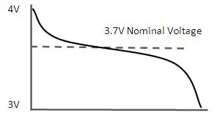
Nominal voltage is the standard voltage level assigned to electrical equipment or systems for identification. It helps ensure compatibility, performance, and safety across devices without indicating actual operating voltage, which may vary slightly.


What is Nominal Voltage?

Nominal voltage refers to the labelled voltage value of an electrical system or device.

✅ Represents standard system voltage, not an  exact measurement

✅ Helps match equipment compatibility and safety standards

✅ Common in power distribution, residential, and industrial systems


Nominal voltage (NV) is a vital aspect of electrical systems, serving as a reference point for designing, manufacturing, and testing equipment. Additionally, it affects the performance, efficiency, and safety of electrical systems, with voltage regulation ensuring that voltage levels (V) remain within acceptable tolerances. Understanding the differences between nominal voltage, operating voltage (OV), and rated voltage (RV) is crucial for professionals and enthusiasts to ensure the effective operation and maintenance of electrical systems. To better understand how nominal voltage fits within broader system design, see our comprehensive overview on voltage.

It is vital to understand the definition and importance of nominal voltage in electrical systems. NV refers to the standard voltage value assigned to an electrical system, typically the voltage that electrical equipment is designed to operate under normal conditions. This value is crucial because it serves as a reference point for designing, manufacturing, and testing electrical equipment to ensure satisfactory performance. Maintaining voltage stability is essential—learn how voltage drop impacts performance and how to accurately calculate it.

Determining nominal voltage for electrical systems involves considering factors such as the type of equipment being used, the overall power requirements, and the voltage standards set by industry organizations. In some cases, the NV is set by the equipment manufacturer, while in others, it depends on the power grid's Voltage levels. Standard nominal voltages have been established to streamline equipment design and manufacturing processes. Use our voltage drop calculator to determine how wiring distance and load affect nominal voltage in real applications.

The terms NV, OV, and RV often appear in discussions about electrical systems. While they may seem interchangeable, each has a distinct meaning. As previously mentioned, nominal voltage is the standard voltage value designated for an electrical system. On the other hand, OV is the actual voltage at which equipment functions during operation. Similar to nominal voltage, RV refers to the maximum voltage at which equipment can operate continuously without sustaining damage. See how voltage regulators are used to maintain nominal levels and protect sensitive equipment.

Nominal voltage has a direct impact on the performance of electrical systems. Equipment designed for specific NVs operates safely within a particular voltage range. Operating outside this range can result in equipment damage, decreased efficiency, and even electrical fires. Therefore, it is essential to maintain the voltage levels as close as possible to the NV. Our guide to what is voltage explains the differences between nominal, operating, and actual voltage in power systems.

Electrical systems worldwide adhere to common national voltage (NV) standards for alternating (AC) and direct (DC) systems. For AC systems, NV  ranges include 110V, 220V, and 380V, while DC systems typically have NVs of 12V, 24V, or 48V. These standardized voltage levels enable the compatibility and interoperability of electrical equipment across various regions and industries. Learn how wattmeters and voltmeter tools help monitor nominal and real-time voltage values in field diagnostics.

Voltage regulation plays a critical role in controlling an electrical system's output voltage to ensure it remains within the acceptable voltage tolerance. Voltage regulation can be achieved through various means, including transformers, voltage regulators, and software algorithms in modern power systems. By maintaining NV, the electrical system The voltages more efficiently and safely, ensuring the longevity of the equipment.

The voltage tolerance is the range of voltage deviation from the nominal voltage value within which equipment can still operate effectively and safely. Different electrical systems have different voltage tolerances depending on the nature of the equipment and its intended use. For instance, a residential electrical system may have a voltage tolerance of +/- 5%, while an industrial system might tolerate a deviation of +/- 10%. Maintaining the acceptable V tolerance is crucial for the satisfactory operation of electrical equipment.


Nominal Voltage (NV) vs Operating Voltage (OV)

Nominal voltage and OV are two related yet distinct concepts in electrical engineering systems. Understanding the different essentials to ensure electrical systems' safe and efficient operation.

Nominal voltage refers to the standard or reference voltage level assigned to an electrical system, circuit, or device. It is the ideal voltage at which the equipment is designed to operate under normal conditions. NV is a baseline value that allows manufacturers, engineers, and technicians to design, test, and rate electrical equipment consistently.

Conversely, OV is the actual voltage level at which a particular electrical system, circuit, or device is functioning during real-time operation. Unlike nominal voltage, OV can fluctuate due to factors such as load changes, temperature variations, and power supply issues. Although electrical equipment is designed to operate optimally within a specified voltage range around the nominal voltage, slight variations in the operating V are often unavoidable.

In essence, NV serves as the benchmark or target voltage level, while OV reflects the real-world voltage conditions experienced by the electrical equipment. To ensure the efficient and safe operation of electrical systems, it is crucial to maintain the OV as close as possible to the NV. When the operating voltage falls within the acceptable voltage tolerance range, electrical equipment can function efficiently and safely without the risk of damage or performance degradation. Discover how alternating current systems rely on standardized nominal voltages like 120V or 240V for safe and consistent operation.


Nominal Voltage (NV) vs Rated Voltage (RV)

Nominal voltage and RV are related terms in electrical engineering but have distinct meanings and implications. Understanding the difference between the two is crucial for designing, operating, and maintaining electrical systems and devices properly. Differences between high voltage, medium voltage, and low voltage categories are based on standardized nominal values used in system classification.

It refers to the standard or reference voltage level assigned to an electrical system, circuit, or device. It is the ideal voltage at which the equipment is designed to operate under normal conditions. NV serves as a baseline value that enables manufacturers, engineers, and technicians to design, test, and rate electrical equipment consistently across various industries and applications.

On the other hand, RV is the maximum voltage at which an electrical device or component can operate continuously without incurring damage or experiencing a significant reduction in performance. RV is a critical parameter to ensure electrical equipment's safe and efficient functioning. Operating an electrical device within its RV range prevents excessive stress on the device, thereby reducing the risk of failure or shortened lifespan. Understanding the concept of electrical resistance is key to managing voltage drop and maintaining nominal voltage across circuits.

Nominal voltage is the target or reference Voltage level for the design and operation of electrical systems. In contrast, RV defines the maximum allowable Voltage for the continuous operation of electrical equipment. To ensure the efficient and safe performance of electrical systems, it is essential to maintain the operating voltage within the acceptable voltage tolerance range around the nominal voltage and not exceed the RV.  The relationship between power factor and nominal voltage affects system efficiency, especially in industrial electrical networks.


Related Articles


View more

Norton's Theorem

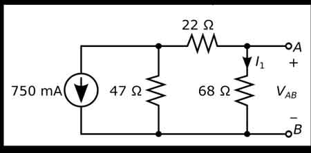
Norton’s Theorem simplifies electrical circuit analysis by reducing any complex linear network to an equivalent current source in parallel with a resistor, enabling easier calculation of load current, evaluation of resistance, and solving practical problems.


What is Norton’s Theorem?

Norton’s Theorem states that any linear electrical network with sources and resistances can be reduced to an equivalent current source in parallel with a single resistor.

✅ Represents complex circuits as a simple current source and resistor

✅ Simplifies load current and resistance calculations

✅ Enhances circuit analysis for power systems and electronics


Understanding Norton's Theorem

Norton's Theorem is a foundational principle in electrical engineering, used to simplify the analysis of linear electronic circuits. This theorem, often taught alongside Thevenin's Theorem, provides a practical method for reducing complex circuits into a manageable form. The main insight of Norton's Theorem is that any two-terminal linear circuit, regardless of its internal complexity, can be represented by an ideal current source in parallel with a single resistor. This transformation does not alter external circuit behavior, making calculations and predictions about circuit performance far more straightforward. To fully grasp circuit simplification methods like Norton’s Theorem, it helps to start with a foundation in basic electricity.

Norton’s Theorem states that any linear electrical network can be simplified into a Norton equivalent circuit, making analysis more manageable. This representation is similar to an equivalent circuit consisting of a single current source and parallel resistance, allowing engineers to determine load behavior with ease. By calculating the total resistance of the network and combining it with the Norton current, complex problems become straightforward, enabling accurate predictions of circuit performance in both educational and real-world applications.


How Norton's Theorem Works

To use Norton's Theorem, engineers follow a step-by-step process:

  1. Identify the portion of the circuit to simplify: Usually, this means the part of the circuit as seen from a pair of terminals (often where a load is connected).

  2. Find the Norton current (IN): This is the current that would flow through a short circuit placed across the two terminals. It's calculated by removing the load resistor and finding the resulting current between the open terminals.

  3. Calculate the Norton resistance (RN): All independent voltage and current sources are deactivated (voltage sources are shorted, current sources are open-circuited), and the resistance seen from the open terminals is measured.

  4. Draw the Norton equivalent: Place the calculated current source (IN) in parallel with the calculated resistor (RN) between the terminals in question.

  5. Reconnect the load resistor: The circuit is now simplified, and analysis (such as calculating load current or voltage) is far easier.

Calculating Norton resistance often relies on principles such as Ohm’s Law and electrical resistance.


Why Use Norton's Theorem?

Complex electrical networks often contain multiple sources, resistors, and other components. Calculating the current or voltage across a particular element can be difficult without simplification. Norton's Theorem allows engineers to:

  • Save time: By reducing a circuit to source and resistance values, repeated calculations for different load conditions become much faster.

  • Enhance understanding: Seeing a circuit as a source and parallel resistor clarifies key behaviors, such as maximum power transfer.

  • Test different scenarios: Engineers can quickly swap different load values and immediately see the effect without having to recalculate the entire network each time.

Understanding how current behaves in different networks connects directly to the study of direct current and alternating current.


Comparison to Thevenin’s Theorem

Norton's Theorem is closely related to Thevenin's Theorem. Thevenin's approach uses a voltage source in series with a resistor, while Norton's uses a current source in parallel with a resistor. The two equivalents can be converted mathematically:

  • Thevenin equivalent resistance (RTH) = Norton equivalent resistance (RN)
  • Norton current (IN) = Thevenin voltage (VTH) divided by Thevenin resistance (RTH)
  • Thevenin voltage (VTH) = Norton current (IN) times resistance (RN)

Engineers applying Norton’s Theorem also draw on related concepts such as equivalent resistance and impedance to analyze circuits accurately.


Real-World Example

Suppose you need to know the current flowing through a sensor in a larger industrial power distribution board. The network supplying the sensor includes many resistors, switches, and sources. Applying Norton's Theorem, you can remove the sensor and find:

  1. The short-circuit current across its terminals (Norton current)
  2. The combined resistance left in the circuit (Norton resistance)

Once you reconnect the sensor and know its resistance, you can easily analyze how much current it will receive, or how it will affect circuit performance under different conditions.

For a deeper understanding, exploring electricity and magnetism reveals how fundamental laws, such as Faraday’s Law and Ampere’s Law, support the theory behind circuit transformations.


Applications of Norton's Theorem

  • Power system analysis: Used by utility engineers to study how changes in distribution, like maintenance or faults, impact circuit behavior.

  • Electronic device design: Common in transistors, op-amps, and other components to simplify input and output circuit analysis.

  • Fault diagnosis and protection: Helps quickly estimate fault currents for setting up protective devices in grids.

  • Education: Essential in electrical engineering curricula to develop problem-solving skills.


Limitations of Norton's Theorem

While powerful, Norton's Theorem is limited to linear circuits and cannot be directly applied to circuits with non-linear components (such as diodes or transistors in their non-linear regions). Additionally, it is only applicable between two terminals of a network; for systems with more terminals, additional techniques are required.

Norton's Theorem remains a valuable tool for engineers and students, offering clarity and efficiency in analyzing complex circuits. By transforming intricate arrangements into simple source-resistor pairs, it enables faster design iterations, troubleshooting, and optimized system performance. Whether you're analyzing a power distribution panel or designing integrated circuits, understanding and applying Norton's Theorem is an essential skill in the electrical field.


Related Articles


View more

Kirchhoff's Law

Kirchhoff's Law, comprising the Current Law (KCL) and Voltage Law (KVL), governs electrical circuits by ensuring charge conservation and energy balance, essential for analyzing current flow, voltage drops, and network behaviour.


What is Kirchhoff's Law?

Kirchhoff's law is an essential principle in the analysis of electrical circuits, enabling a comprehensive understanding of the behaviour of complex circuits.

✅ Defines relationships between currents and voltages in electrical circuits

✅ Ensures conservation of charge (KCL) and energy (KVL) in networks

✅ Essential for analyzing and solving complex circuit problems

It consists of two fundamental rules, Kirchhoff's Current Law (KCL) and Kirchhoff's Voltage Law (KVL), which are intrinsically linked to other electricity laws, such as Ohm's law.  Kirchhoff’s Law works closely with Ohm’s Law Formula to calculate voltage drops, currents, and resistance in electrical networks.

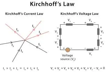
Kirchhoff's Current Law (KCL) - Also known as the first Kirchhoff's law or Kirchhoff's junction rule, KCL states that the sum of the currents entering a junction in a circuit is equal to the sum of the currents leaving the junction. Mathematically, it can be expressed as:

ΣI_in = ΣI_out

KCL is based on the principle of the conservation of charge, asserting that charge can neither be created nor destroyed. In practical terms, KCL means that, at any given point in a circuit, the total current entering must equal the total current leaving, ensuring a continuous flow of electric charge. Understanding Basic Electricity provides the foundation for applying Kirchhoff’s Current Law and Voltage Law to real-world circuit analysis.

Kirchhoff's Voltage Law (KVL) - Also known as the second Kirchhoff's law or Kirchhoff's loop rule, KVL states that the sum of the voltage gains and losses (potential differences) around any closed loop in a circuit is zero. Mathematically, it can be expressed as:
ΣV_rise = ΣV_drop

KVL is based on the principle of the conservation of energy, indicating that energy cannot be created or destroyed but can only be converted from one form to another. In electrical circuits, KVL implies that the total voltage supplied in a loop equals the total voltage drop across all components, ensuring that energy is conserved. Accurate circuit calculations require a clear grasp of Electrical Resistance and how it impacts voltage distribution across components.


Relation to Other Electricity Laws

The most significant connection between Kirchhoff's and other electricity laws is Ohm's law, which defines the relationship between voltage, current, and resistance in an electrical circuit. Ohm's law can be expressed as:

V = IR

When analyzing a circuit using Kirchhoff's laws, Ohm's law is often employed to calculate unknown quantities such as voltage drops, currents, or resistance values. By combining Kirchhoff's laws with Ohm's law, a complete understanding of the behaviour of electrical circuits can be achieved, facilitating efficient design, troubleshooting, and optimization. Applying Kirchhoff’s principles is easier when you understand key Electrical Terms used in engineering and troubleshooting.


History

Gustav Robert Kirchhoff, a German physicist, made significant contributions to understanding electrical circuits by establishing two fundamental laws: Kirchhoff's Voltage Law (KVL) and Kirchhoff's Current Law (KCL). These laws are essential tools for circuit analysis, enabling engineers to design and troubleshoot electrical networks efficiently. In addition to resistance, Capacitance plays a vital role in determining circuit behavior, especially in AC systems.

KVL, also known as the loop rule, states that the algebraic sum of all the voltages around a closed loop equals zero. This principle is derived from the conservation of energy, which ensures that no energy is lost within a closed system. In essence, KVL states that the energy supplied to a circuit is equal to the energy consumed by the components in that circuit. Therefore, when solving problems using KVL, it is essential to consider voltage drops across resistive elements like resistors and voltage rises due to sources like batteries or generators.

On the other hand, KCL, or the junction rule, states that the algebraic sum of currents entering a junction (node) in a circuit is equal to the sum of currents leaving the same junction. This law is a consequence of the conservation of charge, which posits that charge cannot be created or destroyed within an electrical circuit. KCL ensures that the total charge entering and leaving a node remains constant, with the currents (I1, I2, I3, I4, I5) balancing each other. Knowledge of Voltage Drop is essential when using KVL to assess energy losses in electrical circuits.

The significance of these laws in electrical networks lies in their versatility, as they can be applied to a wide range of circuits, from simple series and parallel circuits to more complex electrical networks. Kirchhoff's laws can be employed in conjunction with Ohm's Law, which states that the current through a conductor is proportional to the voltage across it and inversely proportional to its resistance. Using Kirchhoff's and Ohm's Law, engineers can analyze various aspects of a circuit, including voltage drops, current flow, and power distribution.

When analyzing series and parallel circuits, his laws offer valuable insight into the behaviour of electrical components. In series circuits, the current remains constant throughout the entire loop, while the voltage drops across each resistor are proportional to their respective resistances. The voltage across each branch is constant in parallel circuits, but the current is divided among the parallel resistors according to their resistances. By applying KVL and KCL to these configurations, engineers can determine the optimal arrangement of components for a given application.

To illustrate the application of his laws, consider a simple example. Imagine a circuit with a battery, two resistors in series, and a capacitor in parallel with the second resistor. By applying KVL and KCL, we can determine the voltage drop across each resistor, the current flow through each branch, and the voltage across the capacitor, enabling us to analyze the circuit's behaviour under various conditions.

Despite their usefulness, his laws have some limitations and assumptions. For instance, they assume that the components in a circuit are ideal, meaning they have no internal resistance or capacitance. Additionally, they don't account for the effects of electromagnetic fields or the finite speed of signal propagation in AC circuits. However, these limitations are often negligible in many practical applications, as they only marginally impact circuit performance. For a deeper historical context, explore the History of Electricity and the contributions of Gustav Kirchhoff to modern circuit theory.


Related Articles


View more

What is Open Circuit Voltage? Explained

Open circuit voltage is the potential difference measured across the terminals of a device when no external load is applied. Common in batteries, solar cells, and electrical circuits, it helps evaluate performance, efficiency, and voltage characteristics.


What is Open Circuit Voltage?

It is the maximum voltage measured across terminals when no current flows in the circuit, providing a baseline for performance evaluation.

✅ Indicates battery and solar cell efficiency

✅ Helps assess electrical circuit performance

✅ Defines voltage without current flow

What is open circuit voltage? Often abbreviated as OCV, is an essential concept within electrical engineering, particularly relevant to professionals handling electrical systems or devices. Defined as the electrical potential difference between two points in a circuit when no current flows, OCV represents the maximum voltage achievable without applying a load. For electrical workers, understanding OCV is crucial, as it enables the evaluation of power sources and the identification of potential issues within a circuit before engaging with it under load. Knowledge of OCV benefits electrical workers by providing insights into system readiness, ensuring operational safety, and facilitating troubleshooting for optimal equipment performance. Understanding basic electricity is the foundation for grasping what open circuit voltage means, since it defines how voltage behaves when no current flows.


Determining Open Circuit Voltage

OCV can be measured using instruments like digital multimeters, which provide readings of the maximum electrical potential in the circuit. When conducting a test, it’s essential to measure the resistance between two terminals with no current flow. For instance, if a circuit is connected to a 12-volt battery with no load, the multimeter will display the OCV, which typically matches the battery’s maximum voltage. Similarly, in a solar cell, the OCV provides an indication of the maximum power it can generate when fully charged. Such measurements are helpful in evaluating the state of charge and operational status, providing valuable data to maintain system health. A solid grasp of electrical resistance is also critical, as resistance affects how potential differences are measured when a circuit is open.


Open Circuit Voltage Test

The open-circuit voltage test, also known as the no-load test, is a standard procedure in electrical engineering for assessing a power source's condition when it is not under load. In this test, an engineer connects a voltmeter to the terminals of a circuit to measure the OCV. This process is valuable for detecting issues such as short circuits, high resistance, or compromised wiring, which can lead to performance problems. The results from this test enable electrical professionals to detect weak points in a circuit before it operates under load, ensuring smoother and safer functionality. Open-circuit voltage is directly related to capacitance, as capacitors store electrical potential that can be measured under no-load conditions.


Applications of Open Circuit Voltage 

In practical applications, open circuit voltage is not just a measurement but a vital diagnostic tool. For example, in renewable energy systems, engineers often assess solar cell efficiency by examining its OCV. A solar cell’s OCV indicates its potential output, enabling accurate calculations of energy capacity and state of charge. Understanding OCV also aids in selecting voltage levels appropriate for different components, especially in high-voltage systems where matching component capacity is essential. In this way, OCV serves as a baseline for electrical potential, enabling engineers to optimize systems for both performance and safety. Engineers often compare OCV with direct current behavior, where stable voltages are easier to measure without the influence of alternating loads.

The concept of OCV has safety implications. By knowing the maximum potential voltage in a circuit before activating it, engineers can implement safeguards to avoid overloads or shorts that might occur under load. In electrical troubleshooting, measuring OCV allows for the identification of circuits that aren’t performing optimally, pinpointing faults or abnormal resistance that could lead to hazards. Hence, for electrical workers, mastering OCV measurement is not only about system performance but also about adhering to safety standards that protect both personnel and equipment.


Frequently Asked Questions


What is Open Circuit Voltage?

Open circuit voltage refers to the electrical potential, or maximum voltage, present between two conductors in a circuit when there is no active current flowing. This concept is applicable to both direct current (DC) and alternating current (AC) circuits. In DC systems, the OCV remains stable at a maximum level when no load is connected. In AC circuits, OCV may vary depending on factors such as load fluctuations and circuit design. The measurement of OCV is crucial for determining the performance of various devices, including solar cells, where the state of charge can be observed by checking the OCV. Electrical engineers and technicians can use this information to diagnose issues and assess the readiness of systems for operation. In 3-phase electricity systems, knowing the open circuit voltage helps engineers ensure balance and reliability before load conditions are applied.


Why Open Circuit Voltage Matters

For anyone working in electrical engineering, understanding open-circuit voltage is essential for designing and troubleshooting systems. OCV indicates the maximum voltage a circuit can sustain, helping engineers select compatible components and design for peak efficiency. For instance, when assessing a solar cell, the OCV helps identify the electrical potential it can generate without applying any load. In this way, OCV is a guide to the expected performance under load-free conditions, ensuring that devices will perform within specified limits when placed in actual operation. The concept also closely relates to active power, as OCV provides a baseline for calculating the amount of real power a system can deliver once current begins to flow.


Does open circuit voltage change with temperature?

Yes, temperature can affect open circuit voltage. For example, solar cells typically show a decrease in OCV as temperature rises, which impacts efficiency and energy output.


Is the open circuit voltage always equal to the source voltage?

Not always. While OCV often matches the nominal source voltage, internal resistance, aging, or chemical changes in a battery can cause the measured value to differ slightly.


Can open circuit voltage predict battery health?

OCV can give an indication of a battery’s state of charge, but it is not a complete measure of health. Additional tests, such as load testing, are needed to assess the overall condition.


How does open circuit voltage relate to safety testing?

Measuring OCV before energizing equipment enables engineers to confirm expected voltage levels and prevent hazardous conditions that may arise under load.


Is open circuit voltage used in AC systems as well as DC?

Yes, OCV applies to both AC and DC systems. In AC circuits, variations may occur depending on the design and frequency, whereas DC systems typically provide a stable maximum value.


What is open circuit voltage? Open circuit voltage is more than just a technical measurement; it is a vital reference point for understanding the behavior of batteries, solar cells, and electrical circuits under no-load conditions. By measuring OCV, electrical professionals gain valuable insights into efficiency, reliability, and safety before current flows, ensuring systems are prepared for real-world operation. Whether applied in renewable energy, troubleshooting, or equipment testing, open circuit voltage provides the foundation for sound engineering decisions and safer electrical practices.


Related Articles


View more

Equivalent Resistance

Equivalent resistance is the total resistance of a circuit that simplifies multiple resistors into a single resistor. It is calculated differently for series and parallel circuits, helping determine current flow, voltage distribution, and overall power consumption in electrical networks.


What is Equivalent Resistance?

Equivalent resistance is a crucial concept for individuals working with electrical circuits. It: 

✅ Represents the single resistance that replaces multiple resistors in a circuit.

✅ Simplifies calculations of current, voltage, and power.

✅ Found using series or parallel formulas based on resistor arrangement.

By mastering the calculation methods for series and parallel circuits, understanding the relationship with Ohm's law, and applying Kirchhoff's laws in more complex situations, you can efficiently analyze and design electrical systems that meet the requirements of various applications. Furthermore, by incorporating equivalent resistance calculations into your skillset, you'll be better prepared to tackle the exciting challenges presented by the ever-evolving world of electronics and power systems.


Equivalent Resistance in Series vs. Parallel Circuits

Configuration Formula Key Characteristics Example Calculation
Series R_eq = R1 + R2 + R3... Same current flows through all resistors; total resistance increases; voltage drop varies across components. For R1=4Ω, R2=6Ω: R_eq = 4Ω + 6Ω = 10Ω
Parallel 1/R_eq = 1/R1 + 1/R2 + 1/R3... Same voltage across each resistor; total resistance decreases; current divides among paths. For R1=4Ω, R2=6Ω: 1/R_eq = 1/4 + 1/6 = 0.416 → R_eq ≈ 2.4Ω

To calculate the equivalent resistance of a network, it is often necessary to determine the sum of the individual resistances. This involves adding the resistance values of each individual resistor in the network, providing a baseline for further calculations. This is a resistance formula for a single resistor, as well as for calculating resistors connected in parallel or in series.

Electrical resistance (R) is a measure of the opposition to the flow of electric current within a circuit. It is determined by the material and dimensions of the conductor, as well as the temperature and other environmental factors. It is measured in ohms (Ω), with lower R indicating greater conductivity and vice versa.


Equivalent Resistance Formula

When a group of resistors is connected end-to-end, they form a series. In a series circuit, the total resistance is equal to the sum of the individual Rs, as current must flow through each resistor in turn. The equivalent resistance of a series circuit is calculated by adding the values of each individual resistor:

Req = R1 + R2 + R3 + ...

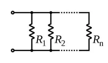
Resistors connected across the same potential difference, or applied voltage, are referred to as being connected in parallel. In a parallel circuit, the total R is less than the R of any individual resistor as the current divides among the resistors. The equivalent resistance of a parallel circuit is calculated using the reciprocal formula:

1/Req = 1/R1 + 1/R2 + 1/R3 + ...

Equivalent resistance is the single R value that can replace a group of resistors in a circuit, offering the same overall R. This simplifies circuit analysis and allows for more straightforward calculations of current and voltage values.

Ohm's law is an essential principle in electronics and relates closely to equivalent resistance. Ohm's law states that the current (I) flowing through a resistor is directly proportional to the applied voltage (V) and inversely proportional to the R. The equation is:

V = IR

By calculating equivalent resistance for a given circuit, we can use Ohm's law to determine the overall current flowing through the circuit and the voltage drops across each resistor.


Series and parallel circuits exhibit different properties when it comes to equivalent resistance. In series circuits, the overall R increases with the addition of more resistors, which means the total current will decrease. In parallel circuits, adding more resistors results in a decrease in total resistance, causing an increase in total current. Understanding these differences is crucial for designing circuits that meet specific electrical requirements.


Kirchhoff's Law

Kirchhoff's laws are another essential tool for calculating equivalent resistance in more complex circuits that cannot be simplified as purely series or parallel. Kirchhoff's current law (KCL) states that the sum of currents entering a junction in a circuit must equal the sum of currents leaving the junction. Kirchhoff's voltage law (KVL) asserts that the sum of the voltages around any closed loop in a circuit must equal zero. By applying these laws, we can create a system of equations to solve for unknown resistance values in a network, ultimately determining the equivalent resistance.


Real-World Applications

Real-world applications of equivalent resistance can be found in various fields, such as electronics, power distribution, and telecommunications. For example, various components have different R values in electronic devices, such as smartphones. Calculating the equivalent resistance enables engineers to design efficient power management systems, ensuring optimal performance and extended battery life. In power distribution networks, equivalent resistance calculations are essential for determining voltage drops and current values across transmission lines, enabling the design of efficient and reliable power delivery systems.

Understanding equivalent resistance is vital for professionals and students who deal with electrical circuits. From simplifying complex networks to designing efficient circuits, equivalent resistance plays a central role in analyzing and developing modern electronic systems. Familiarity with this concept and associated principles like Ohm's law and Kirchhoff's laws ensures a strong foundation for anyone working with electronics, power systems, and telecommunications.


Technology Advances

As technology advances, the importance of equivalent resistance in designing and analyzing new devices and systems will only grow. Calculating and understanding equivalent resistance enables engineers to push the boundaries of innovation and improve upon existing systems, resulting in more efficient, high-performance solutions for consumers and industries alike.

To further develop your understanding of equivalent resistance and related concepts, consider exploring the wealth of educational resources available online and in textbooks, as well as seeking hands-on experience through workshops or real-world projects. Applying this knowledge to practical scenarios will enable you to tackle various electrical and electronic challenges.

Related Articles


View more

DC Current - Electricity Explained

DC current delivers unidirectional electron flow with constant polarity, powering circuits, batteries, and electronics; characterized by steady voltage, low ripple, and efficient distribution via rectifiers, converters, and regulated power supplies in electrical engineering.


What Is DC Current?

DC current is unidirectional electron flow with constant polarity, providing steady voltage for efficient power delivery

✅ Provides constant voltage for sensitive electronics and logic circuits

✅ Generated by batteries, fuel cells, solar PV; produced via rectification

✅ Enables precise control in motors, sensors, and industrial automation


DC current is essential to electrical energy, powering devices ranging from small electronic gadgets to electric vehicles. We can appreciate its significance in modern life by understanding its properties, applications, and relationship to other electrical concepts such as voltage, resistance, and Ohm's Law. Despite its limitations in power transmission over long distances, the use of DC current in solar energy systems and electric vehicles continues to demonstrate its vital role in an increasingly electrified world. For a practical primer, the direct current overview clarifies key concepts used in everyday systems today.


Direct current (DC) and alternating current (AC) are the two primary forms of current that power various electrical devices and systems. As the name suggests, direct current flows in a single, unidirectional direction, while alternating current oscillates in direction and magnitude. This article will explore the fundamental concepts of DC current, its applications, and its relationship to other aspects of electricity. For deeper contrasts, the difference between AC and DC guide expands on efficiency, safety, and conversion considerations for designers.

It is the flow of electric charge (electrons) in a consistent direction across a conductor, such as a wire. The consistent flow differentiates it from AC, where the direction of the flow periodically reverses. One of the most significant differences between DC and AC current is their power transmission method. DC systems transmit power at a constant voltage, while AC power alternates at a specific frequency. Complementing this, an accessible alternating current explainer details waveform behavior and frequency effects relevant to grid systems.

Electrical circuits using DC current play an essential role in many everyday devices and systems. Some common applications of DC current include batteries, solar panels, and electronic devices. Batteries are a prime example of a DC power source, as they generate a steady flow of electrons from one terminal to another. Solar panels, on the other hand, convert sunlight into DC electrical energy, which can then be stored in batteries or transformed into AC for use in homes or businesses. If you're new to the topic, this current electricity introduction connects sources like batteries and solar arrays to practical loads in simple terms.

In DC current circuits, voltage and resistance are essential factors influencing the flow of electric charge. Voltage refers to the electric potential difference between two points, whereas resistance represents the opposition to the flow of current. Ohm's Law, a fundamental principle in electrical engineering, states that the current flowing through a conductor between two points is directly proportional to the voltage across those points and inversely proportional to the resistance between them. In other words, the higher the voltage or, the lower the resistance, the greater the current. A concise current reference ties these relationships to measurement practices and typical units used in labs.

DC current also plays a critical role in electric vehicles, where it is converted from high-voltage batteries to the required voltage for the electric motor. This conversion from DC to AC is essential because electric motors typically function on AC power.

DC current presents both advantages and disadvantages. One of its main benefits is its simplicity, as it maintains a constant voltage and current flow, making it easier to work with in electronic devices. Additionally, its unidirectional flow allows for more efficient power storage in batteries. However, one significant drawback is that it could be better suited for long-distance power transmission, as it suffers from substantial power loss over long distances.

The story of electricity would be incomplete without mentioning the famous "Battle of the Currents" between Thomas Edison, a staunch advocate of DC systems, and George Westinghouse, who supported AC systems. Ultimately, AC power emerged as the winner for power distribution due to its ability to transmit power over long distances with minimal energy loss. For historical and conceptual grounding, an electricity definition frames how these terms evolved across scientific practice.


DC Current Calculator Explained

A DC current calculator is a tool that helps to determine the direct current flowing through an electrical circuit based on known values of voltage, resistance, and sometimes power. It is used to simplify and verify calculations related to DC circuits and ensure proper circuit design, maintenance, and troubleshooting. The calculator uses Ohm's Law and the power equation as the basis for its calculations.

Ohm's Law states that the current (I) flowing through a conductor between two points is directly proportional to the voltage (V) across those points and inversely proportional to the resistance (R) between them. The formula is:

I = V / R

In addition to Ohm's Law, the power equation can be used to determine the current in a circuit when the power (P) and voltage (V) are known:

P = IV

By rearranging this formula, we can find the current:

I = P / V

To use a calculator, you will typically input the known voltage, resistance, and/or power values, and the calculator will solve for the unknown variable (in this case, the current). For safe circuit operation, some calculators may provide additional information, such as power dissipation or required resistor wattage. If you need a refresher before using calculation tools, this basic electricity primer reviews units, symbols, and safety fundamentals that prevent common mistakes.

A calculator is especially useful for electrical engineers, technicians, and hobbyists working with DC circuits to verify their calculations or diagnose issues within the circuit. It can help ensure the proper functioning of electronic devices, efficient energy usage, and the safety of the electrical components within a system.


Related Articles

View more

Sign Up for Electricity Forum’s Newsletter

Stay informed with our FREE Newsletter — get the latest news, breakthrough technologies, and expert insights, delivered straight to your inbox.

Electricity Today T&D Magazine Subscribe for FREE

Stay informed with the latest T&D policies and technologies.
  • Timely insights from industry experts
  • Practical solutions T&D engineers
  • Free access to every issue

Download the 2025 Electrical Training Catalog

Explore 50+ live, expert-led electrical training courses –

  • Interactive
  • Flexible
  • CEU-cerified