Overcurrent Protection as a System Safety Function
By William Conklin, Associate Editor
By William Conklin, Associate Editor

Our customized live online or in‑person group training can be delivered to your staff at your location.

What is overcurrent protection? It is a system safety function that limits fault energy when electrical current exceeds safe operating levels, preventing equipment damage, fire, and arc-flash escalation through coordinated interruption.
Overcurrent protection sits quietly in the background of every electrical system, rarely noticed until it fails or is missing. When it performs as intended, abnormal conditions are cleared before they escalate. When it does not, failures tend to be sudden and unforgiving, damaging equipment, interrupting service, and exposing people to serious risk.
Electrical systems are designed around defined limits. Conductors, insulation, and equipment can tolerate only so much current before heat and mechanical stress begin to cause permanent damage. Sometimes that stress develops gradually. Sometimes it appears instantly. In either case, overcurrent protection is designed to detect when those limits are exceeded and to act before damage becomes irreversible.
This function is not about individual components. It governs how the system behaves when normal conditions break down, determining whether faults remain localized or propagate upstream into larger failures.
For a foundational overview of device categories, functions, and use cases, visit Circuit Protection Devices.
In most installations, overloads occur far more often than catastrophic failures. Motors may run longer than expected, bearings may begin to bind, or circuits may slowly accumulate more load than originally planned. Current rises modestly, often only a few times above normal levels, yet the heating effect compounds over time. Left uncorrected, insulation weakens, terminations degrade, and a manageable condition quietly becomes a serious failure.
Stay informed with our FREE Electrical Protection Newsletter — get the latest news, breakthrough technologies, and expert insights, delivered straight to your inbox.
Faults behave very differently. Short circuits and ground faults are violent events driven by extremely high current. Magnetic forces can deform conductors and buswork, insulation can be destroyed in milliseconds, and metal can vaporize. In these situations, delay does not mean more heat. It means physical destruction.
| Condition | Magnitude (× normal current) | Typical Duration | Protection Objective |
|---|---|---|---|
| Motor starting inrush | 3–6× | < 2 s | Allow without tripping |
| Sustained overload | 2–4× | > 10 s | Limit thermal damage |
| Short circuit | 100–200× | < 0.1 s | Interrupt immediately |
The purpose of overcurrent protection is to limit energy let-through, not merely to detect excess current.
Overcurrent protection is achieved through a coordinated set of protective elements rather than a single device. Different elements play different roles depending on voltage level, available fault current, and selectivity requirements.
Some elements respond deliberately, allowing temporary conditions such as motor starting while reacting to sustained heating. Others exist for one purpose only, clearing high-level faults as quickly as possible. Confusing these roles leads to poor outcomes, either nuisance interruptions or inadequate fault clearing when it matters most.
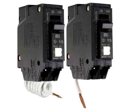
Overcurrent protection devices such as fuses, circuit breakers, and protective relays execute the protection strategy. They are not the strategy itself.
Every overcurrent protection element must be capable of interrupting the maximum available fault current at its location. If a device cannot safely interrupt that current, protection fails catastrophically.
For example, in a 480-volt motor control center with significant available fault current, effective protection depends on rapid detection and interruption before peak let-through energy is reached. When coordination is correct, thermal rise remains within conductor limits, mechanical stress is controlled, and damage is confined to the affected zone.
This outcome depends on coordination, not just device speed.
Selective coordination ensures that the overcurrent protection element closest to a fault clears it first, isolating damage and preserving upstream service. Engineers evaluate coordination using time-current characteristic curves to confirm that devices operate in the intended sequence across the expected fault range.
When coordination is poor, a single fault can escalate into a facility-wide outage. When it is done well, faults are cleared cleanly with minimal disruption and reduced arc-flash exposure.
Electrical codes and standards establish minimum requirements, not complete solutions. Installation rules define the boundaries for selecting and applying overcurrent protection devices, while safety standards address labeling, work practices, and exposure control. Real-world systems still require analysis, especially as modern loads, distributed generation, and power electronics alter fault behavior beyond what prescriptive rules can anticipate.
Protection design remains an engineering judgment, not a checklist exercise.
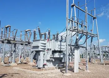
As systems grow in size and complexity, basic overcurrent protection is often supplemented with directional and differential methods. Directional protection becomes essential where power can flow in multiple directions. Differential protection compares the currents entering and leaving a defined zone, allowing extremely fast, selective fault clearing in transformers, generators, and bus systems.
Coordination studies tie these methods together, ensuring protective elements operate in the correct order without unnecessary interruption.
When overcurrent protection is done well, it attracts little attention. Systems operate quietly for decades, faults are cleared cleanly, and damage is limited. When it is done poorly, the consequences are immediate and costly.
Overcurrent protection is ultimately a design and risk-management decision. Once fault behavior, coordination requirements, and asset sensitivity are understood, the next step is applying those principles correctly in real systems. That progression continues through fault current analysis, transformer protection strategy, system-level coordination, and formal training for those responsible for designing, maintaining, or approving protection schemes:
Think you know Electrical Protection? Take our quick, interactive quiz and test your knowledge in minutes.
Advantages To Instructor-Led Training – Instructor-Led Course, Customized Training, Multiple Locations, Economical, CEU Credits, Course Discounts.
Request For QuotationWhether you would prefer Live Online or In-Person instruction, our electrical training courses can be tailored to meet your company's specific requirements and delivered to your employees in one location or at various locations.