Electrical Protection
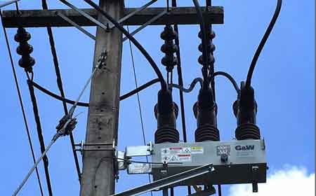
Load Break Switch and the Line Between Switching and Protection
Download Our FREE Electrical Protection Handbook
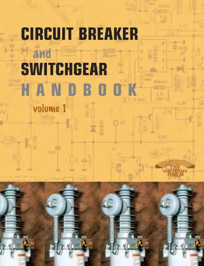
Circuit Breaker And Switchgear Handbook Vol. 1
This 100+ page handbook covers the most important aspects of switchgear design, applications, safety, and maintenance -- giving electrical engineers and contractors the vital information they need to select and specify switchgear and control equipment.
In this edition, we explore the core concepts of circuit breaker functionality, including the various types of breakers such as air, oil, vacuum, and SF6, with a focus on their operating principles and selection criteria. We also provide a thorough understanding of switchgear systems, from low-voltage to high-voltage applications, including their role in isolating and protecting electrical circuits and equipment.
With a focus on real-world applications, Volume 1 covers the latest innovations in circuit breaker technologies, the evolving role of switchgear in smart grids, and the growing importance of energy efficiency and sustainability in the design and operation of electrical protection systems. In addition, this handbook emphasizes industry best practices for installation, testing, and maintenance, helping professionals ensure that their equipment remains safe, reliable, and compliant with regulatory standards.
Latest Electrical Protection Articles
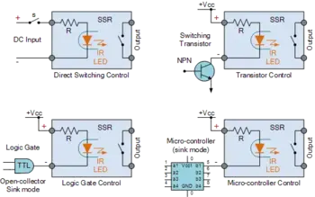
What Are The 7 Reasons to Opt for Solid State Relays?
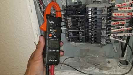
How to Test a Circuit Breaker Safely
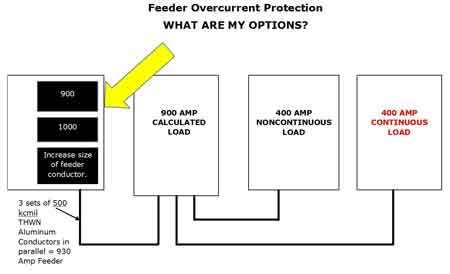
Overcurrent Protection Device Explained
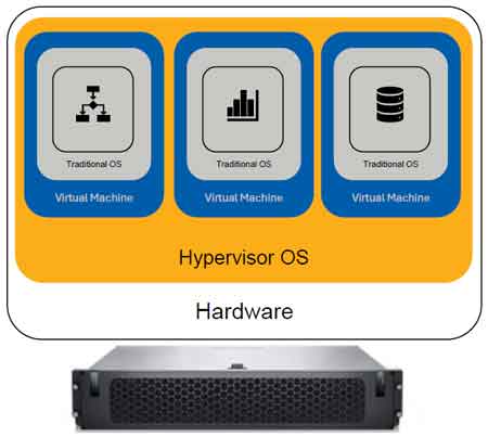
Protection in Electrical System Architecture and Control
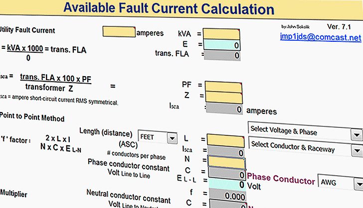
Available Fault Current in Electrical Systems