Current Limiting Fuse
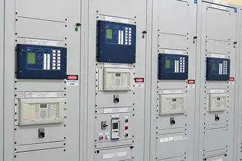
Protective Relay Training - Basic
Our customized live online or in‑person group training can be delivered to your staff at your location.
- Live Online
- 12 hours Instructor-led
- Group Training Available
Download Our OSHA 4475 Fact Sheet – Being Aware of Arc Flash Hazards
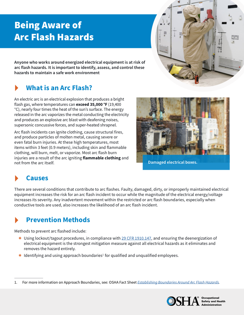
- Identify root causes of arc flash incidents and contributing conditions
- Apply prevention strategies including LOTO, PPE, and testing protocols
- Understand OSHA requirements for training and equipment maintenance
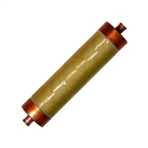
A current limiting fuse protects electrical systems by interrupting fault currents before they reach damaging levels. It limits energy let-through, safeguards transformers, motors, and conductors, and enhances short-circuit protection in medium and high voltage applications.
What is a Current Limiting Fuse?
A current limiting fuse is a protective device that interrupts excessive fault currents quickly to reduce thermal and mechanical damage in electrical circuits.
✅ Limits peak fault current and energy let-through
✅ Protects cables, transformers, and switchgear from damage
✅ Ensures faster system recovery and equipment longevity
Current limiting fuses play a vital role in modern electrical safety and protection systems, acting as precision-engineered overcurrent protection devices that minimize damage during fault events. Their fault current limiting ability reduces the thermal and mechanical stress caused by a prospective fault current, ensuring downstream components remain intact. Engineers evaluate each fuse’s interrupting rating and I²t energy let-through to confirm that it can safely clear high-energy faults without compromising circuit reliability. The proper application of a Current Limiting Fuse also requires selective coordination, allowing only the nearest device to operate during a fault while preserving continuity elsewhere in the system. Together, these performance factors determine how effectively a device safeguards critical assets and maintains overall system integrity.
Basic Protection Relay Training
Request a Free Training Quotation
For a broader understanding of how overcurrent and short-circuit events are controlled, see our guide on overcurrent protection, which complements the role of current limiting fuses in fault current mitigation.
How Does It Work?
A Current limiting fuse is a vital component in modern electrical systems, designed to protect equipment from fault conditions by minimizing the amount of current during a fault. Understanding the operation, benefits, selection criteria, and maintenance practices of electrical installations is crucial for ensuring their safety and efficiency. You can also explore the fundamentals of power system protection to see how current limiting fuses integrate into overall fault current control strategies.
Sign Up for Electricity Forum’s Electrical Protection Newsletter
Stay informed with our FREE Electrical Protection Newsletter — get the latest news, breakthrough technologies, and expert insights, delivered straight to your inbox.
A current limiting fuse is a protection device that interrupts excessive current flow during a fault condition, such as a short circuit, by quickly reducing the fault current to a lower, safer level. This rapid response is achieved through the fuse's special construction, which includes elements that melt quickly when exposed to high fault currents, creating an arc that is rapidly quenched. This action limits the energy let through the circuit, protecting downstream equipment from damage. Discover how protective relays work in conjunction with devices to effectively isolate faults by visiting our overview of protective relay systems.
Types and Classifications of Current Limiting Fuses
Current limiting fuses are classified by how they handle overload and fault conditions. The three main types are:
Full-Range Fuses – Interrupt both overloads and short-circuit currents. Ideal for transformers and feeders that need complete protection.
Backup Fuses – Operate only under high fault currents and require another device, such as a relay or contactor, to protect against low-level overloads. Common in medium-voltage motor and switchgear circuits.
General-Purpose Fuses – Provide protection for most overcurrents but are less sensitive at very low fault levels. Used in general distribution and capacitor bank applications.
Typical ratings include 600 V for low-voltage systems and 2.4 kV to 15 kV for medium-voltage circuits. Choosing the correct type of Current Limiting Fuse ensures proper coordination with equipment such as transformers, motors, and switchgear.
Comparison and Key Features of Current Limiting Fuses
| Feature / Aspect | Current Limiting Fuse | Standard Fuse | Circuit Breaker |
|---|---|---|---|
| Primary Function | Interrupts high fault currents before they reach damaging levels | Breaks circuit when current exceeds rated value | Automatically opens circuit during overload or short circuit |
| Response Time | Extremely fast (within half a cycle) | Moderate (one or more cycles) | Slower mechanical operation |
| Fault Current Limiting | Yes — restricts let-through energy and peak current | No — allows full fault current before blowing | No — interrupts after current peak |
| Protection Level | Excellent short-circuit and overload protection | Basic overload protection | Good for overload, less effective for instantaneous faults |
| Reset Capability | Non-resettable, requires replacement | Non-resettable, requires replacement | Resettable manually or automatically |
| Typical Applications | Transformers, motors, switchgear, and power distribution systems | General-purpose circuits, lighting | Industrial feeders, motor control centers |
| Maintenance Needs | Low — periodic inspection and replacement after operation | Low | Moderate — mechanical wear and calibration required |
| Cost and Simplicity | Cost-effective and simple design | Very inexpensive | Higher cost, more complex installation |
| Compliance Standards | Meets NFPA 70E, IEC, and UL fuse classifications | Meets basic safety standards | Governed by IEC and ANSI breaker standards |
| Key Advantage | Limits peak fault energy to protect downstream equipment and reduce system stress | Simple, low-cost overload protection | Reusable, adjustable, suited for system coordination |
Performance Characteristics of Current Limiting Fuses
Current limiting fuses are defined not only by how they interrupt fault currents, but by how effectively they limit the energy that passes through during a short circuit. Their performance is measured in terms of peak let-through current, I²t (energy let-through), and threshold current, all of which describe the amount of electrical stress the device allows before opening the circuit.
Peak Let-Through Current (Ip)
During a short circuit, a conventional fuse allows the fault current to rise to its natural peak before interrupting. A current limiting fuse, by contrast, interrupts the fault so rapidly that the current never reaches that peak value. The reduced let-through current (Ip) means less magnetic and thermal stress on cables, switchgear, and connected equipment. The lower the Ip, the better the protection.
I²t (Energy Let-Through)
I²t represents the total energy that passes through the Current Limiting Fuse during fault clearing. It is calculated as the square of the current multiplied by the time it takes for the device to clear the fault. Lower I²t values indicate better energy limitation and less heating or mechanical strain on conductors and insulation. Manufacturers often publish pre-arcing and total clearing I²t values that help engineers select the correct device for each circuit’s fault level.
Threshold Current
Every current limiting fuse has a minimum current level, called the threshold current, above which it begins to limit. Below this point, the fuse behaves like a standard device, responding according to its time-current characteristics. Once the threshold is exceeded, the fuse enters its current-limiting region, drastically reducing both current and energy let-through.
Simplified Relationship Between Fault Current and Let-Through Energy
| Fault Current (kA) | Fuse Response Mode | Peak Let-Through Current (kA) | Equipment Impact |
|---|---|---|---|
| 5 | Non-limiting region | ≈ 5 | High energy let-through; possible conductor overheating |
| 15 | Threshold point reached | ≈ 10 | Moderate energy let-through; controlled thermal stress |
| 30 | Fully limiting region | ≈ 12 | Low energy let-through; minimal component damage |
| 50 | Maximum design rating | ≈ 15 | Very low energy let-through; rapid clearing and full protection |
Frequently Asked Questions
What are the Benefits of a Current Limiting Fuse?
The primary benefit of using these devices is their ability to protect equipment by limiting the energy during fault conditions. This capability significantly reduces the potential for damage, minimizes downtime, and enhances overall system safety. Additionally, these devices offer overload protection, ensuring that the system can handle temporary overloads without tripping unnecessarily. Their effectiveness in mitigating magnetic forces during short circuits also contributes to the prolonged lifespan of electrical components. To understand how various devices work together to ensure system reliability, check our page on relay and circuit breaker coordination.
Test Your Knowledge About Electrical Protection!
Think you know Electrical Protection? Take our quick, interactive quiz and test your knowledge in minutes.
- Instantly see your results and score
- Identify strengths and areas for improvement
- Challenge yourself on real-world electrical topics
How Do You Select the Appropriate Current Limiting Fuse for a Specific Application?
Selecting the right current limiting fuse involves several considerations. First, determine the voltage and current ratings required for your specific application. It's essential to match these ratings with the system's requirements to ensure proper protection. Next, consider the class, such as Class RK5, which offers specific characteristics suitable for different applications. Assess the interrupting capacity, which should be higher than the maximum prospective short-circuit current at the point of application. Additionally, evaluate the need for time delay devices, which allow temporary overloads without blowing, thus providing flexibility in system operation.
What are the Differences Between CLFs and Other Types of Fuses?
Current limiting fuses differ from other fuses primarily in their ability to reduce fault currents quickly. Unlike standard types, which may allow higher currents to pass through before blowing, current limiting fuses act almost instantaneously, thus providing superior protection. Designs vary, with current limiting fuses often incorporating advanced materials and construction techniques to achieve their rapid response. Compared to circuit breakers, which may take longer to interrupt fault currents, these devices offer a more immediate solution; however, both are essential in a comprehensive protection strategy. To compare fuse-based systems with other circuit protection devices, review our guide to circuit protection devices for a complete overview of modern electrical safety components.
How Do You Properly Install and Maintain a CLF?
Proper installation and maintenance of current limiting fuses are crucial for their effective operation. Begin by selecting compatible holders that match the class and electrical ratings. Ensure all connections are secure and free from corrosion. During installation, follow manufacturer guidelines to prevent damage to the elements. Regular maintenance involves inspecting devices for signs of wear or damage, such as discoloration or deformation. Periodic testing of the electrical systems can also help identify potential issues before they result in failures.
Current limiting fuses are indispensable in safeguarding electrical systems against fault conditions. By understanding their operation, benefits, and proper selection and maintenance, you can ensure your electrical installations remain protected and efficient. Whether dealing with overload protection or mitigating the impact of short circuits, these fuses offer a wide variety of solutions tailored to different applications. When used correctly, they provide a reliable means of protecting equipment and maintaining system integrity, making them a crucial component in modern electrical systems.
Related Articles
Transformer Protection Explained
Maximum Fault Current Calculation


