Electricity Windmill Explained


Electricity Windmill

Electricity windmill converts wind energy into electrical power via rotor blades, generator, gearbox, and inverter, supporting renewable energy, grid integration, power electronics, and efficient electricity production with modern control systems and variable-speed drives.


What Is an Electricity Windmill?

An electricity windmill converts kinetic wind energy into grid-grade electrical power via a wind turbine system.

✅ Generator, gearbox, and rotor optimize energy capture

✅ Inverter and VFD enable grid-quality AC output

✅ SCADA monitors performance, safety, and fault detection


Electricity windmill Mankind been harnessing the wind's energy for many years. From Holland to traditional farms around the world, old style windmills were used in the past for pumping water through primative irrigation systems or used to grind grain. Then, the wind turned large "sails" which were connected by a long vertical shaft that was attached to a grindnig machine or to a wheel that turned and drew water from a well. Today's wind turbine generators can utilize the clean energy of high wind speeds to turn large metal blades which in turn spins a generator that manufactures electric power. For a deeper overview of modern designs, the resource at windmills for electricity explains key configurations used by utilities today.

Electricity windmill turbines, unlike the machines of old, are mounted on very tall towers in order to capture the most wind energy available. At 100 feet (30 meters) or more above ground, wind turbines can take advantage of the faster and less turbulent wind. Turbines catch the wind's energy with their propeller-like blades. Usually, two or three blades are mounted on a shaft to form a rotor. If you're curious how these rotating blades ultimately power homes, see how turbines generate electricity through step-by-step conversion processes.

A blade acts much like an airplane wing. When the wind blows, a pocket of low-pressure air forms on the downwind side of the blade. The low-pressure air pocket then pulls the blade toward it, causing the rotor to turn. This is called lift. The force of the lift is actually much stronger than the wind's force against the front side of the blade, which is called drag. The combination of lift and drag causes the rotor to spin like a propeller, and the turning shaft spins a generator to make power. The rotating shaft must be matched to an electricity generator with appropriate gearing and controls to optimize output.

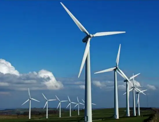
In recent years, governments have invested enormous amounts of (taxpayer) money in electricity windmill "wind farms" to generate large amounts of energy from large and small wind turbines that take advantage of high winds. These wind systems or energy systems use wind turbine power to create electricity.  Other energy sources like solar power do not produce as much electricity. The only problem with wind generated power is that when the wind stops, so does the generator and therefore the electric power production. Electric power cannot be produced and stored for consumption later. Therefore, wind power can only be counted on mostly when the wind is blowing at optimal speeds and only in locations where the prevailing winds are such that it makes economic sense to build these power plants and this may not be when and where the power is needed. Grid planners track regional electricity production profiles to determine how much wind capacity can be integrated without compromising reliability. As part of a balanced portfolio, policy makers also evaluate alternative electricity options that can complement variable wind resources.

Stand-alone electricity windmill turbines are typically used for water pumping or communications. However, homeowners, farmers, and ranchers in windy areas can also use wind turbines as a way to cut their power bills. For off-grid ranch operations, understanding the interplay between pumps and water electricity systems helps size batteries and controllers correctly.

Small electricity windmill systems also have potential as distributed energy resources. Distributed energy resources refer to a variety of small, modular power-generating technologies that can be combined to improve the operation of the electric power delivery system. In some regions, small-scale hydroelectricity can serve as a firm companion to wind in distributed portfolios.


Related Articles

Related News

Generate Electricity From Different Sources - Thermal, Nuclear, Renewable Energy

Generate electricity via power generation methods: generators, turbines, photovoltaics, fuel cells, and microgrids; optimized by inverters, AC/DC conversion, smart grid control, energy storage, high-efficiency transmission, and reliable distribution networks integration.


What Is Generate Electricity?

Generate electricity converts energy to electric power using generators, turbines, and inverters for grid supply.

✅ Electromechanical conversion with synchronous or induction generators

✅ Power electronics: rectifiers, inverters, MPPT, AC/DC conversion

✅ Sources: PV, wind, hydro, gas turbines; grid-tied or microgrid


There are several ways to generate electricity. There are "thermal" methods like coal, oil, natural gas, peat, biomass - in all these cases, the energy that is trapped in the form of carbon (found in the ground in the form of fossil fuels) is released by heating the carbon. The problem, as we all know too well, is that the breakdown of carbon through burning it is the by product of gases such as carbon dioxide, a main contributor to global warming. But that is not all. When we burn carbon, there are other pollutants that are released into the atmosphere like sulphur dioxide and nitrous oxide. These chemicals are the principal contributors to acid rain. For a broader overview of these processes, see how electricity generation works across different fuel types.

We also produce electricity by non-fossil fuel methods by using uranium in nuclear fission "reactors" to create enough heat to boil water, which in turn produces large quantities of high pressure steam. This steam turns a turbine which turns a generator that manufactuers electic power through the conversion of mechanical energy into electrical energy. This sequence illustrates how electricity is generated from thermal sources in practice.

There is more than one renewable source of energy to generate electricity, by using solar panels to convert sunlight and wind energy to convert kinetic energy into electric power. In any case dependable power generation, transmission and distribution is critical for providing heat, light and power for human activities. Electric power has been generated for the purpose of powering human technologies for at least 120 years from various sources of potential energy. The first power plants were run on wood, while today we rely mainly on oil, natural gas, coal, hydroelectric and nuclear power and a small amount from hydrogen, solar energy, tidal harnesses, wind generators, and geothermal sources. Many utilities are expanding portfolios with alternative electricity options to meet emissions targets.


Methods To Produce Electric Power

Understanding the landscape of sources of electricity helps frame the methods described below.

Rotating turbines attached to electrical generators produce most commercially available electricity. Turbines may be driven by using steam, water, wind or other fluids as an intermediate energy carrier. The most common usage is by steam in fossil fuel power plants or nuclear power plants, and by water in hydroelectric dams. Alternately, turbines can be driven directly by the combustion of natural gas or oil. Combined cycle gas turbine plants offer efficiencies of up to 60%. They generate power by burning natural gas in a gas turbine and use residual heat to generate additional electric power from steam. Wind turbines create power by using the wind. Solar updraft towers use wind that is artificially produced inside the chimney by heating it with sunlight. Solar parabolic troughs and solar power towers concentrate sunlight to heat a heat transfer fluid that is used to produce steam to turn a turbine. In all these configurations, the core electricity generator converts rotational energy into electrical output.

Within wind applications, the modern electricity windmill integrates power electronics and control systems to maximize capacity factor.

Small power generators are often powered by reciprocating engines burning diesel, biogas or natural gas. Diesel engines are often used to create power, usually at low voltages. Biogas is often combusted where it is produced, such as a landfill or wastewater treatment plant, with a reciprocating engine or a microturbine, which is a small gas turbine. These distributed assets play a growing role in overall electricity production for remote sites and microgrids.


Related Articles

View more

Wireless Electricity

Wireless electricity transmits power without wires using electromagnetic fields, such as magnetic resonance or microwave transmission. It enables charging devices remotely, powering sensors, and improving efficiency in smart grids, EVs, and wireless charging systems.


What is Wireless Electricity?

Wireless electricity refers to the transmission of electrical energy without physical conductors like wires.

✅ Powers devices through electromagnetic fields, like inductive coupling

✅ Enables contactless charging in consumer electronics and EVs

✅ Supports smart grids, IoT, and remote sensors with flexible energy delivery

Wireless electricity, also known as wireless power transmission, was first conceptualized by Nikola Tesla, a pioneer in the field of alternating current (AC) electricity. Tesla’s groundbreaking experiments at Colorado Springs in 1899 showcased how power could be transmitted without wires using a magnetic field. He used a Tesla coil to transmit 100 million volts of high power over a distance of 26 miles, wirelessly powering 200 light bulbs and an electric motor. His vision was to develop a wireless system capable of transmitting power over long distances with minimal energy loss.

Tesla’s system relied on a high-frequency alternating current and magnetic resonance to transmit power wirelessly. His experiments with the Tesla coil laid the groundwork for modern wireless technologies, including short-range wi

reless power transmission systems, such as wireless charging pads and Wi-Fi routers. Wireless charging pads today utilize magnetic fields to transmit power to devices, a concept similar to Tesla’s idea of harnessing the Earth’s resonance to transmit power over longer distances. Tesla’s vision extended beyond short-range wireless systems—he dreamed of a global system where energy flows freely through the air without requiring a direct line of sight.

Tesla’s experiments also demonstrated the efficiency of wireless systems. The Tesla coil could transmit power wirelessly to fluorescent light bulbs even when they were several feet away from the coil. This concept of powering devices wirelessly has evolved over time, with companies like Wi-Charge developing systems to transmit power wirelessly to small devices. In Tesla’s time, he envisioned a world where any amount of power could be transmitted wirelessly across the globe. However, financial struggles eventually led to the abandonment of his wireless power transmission projects, including the unfinished Wardenclyffe tower on Long Island. Devices powered wirelessly still rely on efficient energy flow, making concepts such as electrical resistance and impedance crucial to design and performance.

Despite Tesla’s challenges, modern advancements have kept his vision alive. Short-range wireless power transmission systems, like those used in Wi-Fi routers and wireless charging pads, are now commonplace. These technologies utilize magnetic fields to transmit power wirelessly over short distances, offering a practical solution for wirelessly charging devices such as smartphones and laptops. Wi-Charge is exploring the potential of wirelessly charging devices without requiring close contact, enabling more flexible and efficient energy distribution. Tesla’s coil and modern systems like Wi-Charge operate based on resonant principles, closely related to inductance and capacitance.


Modern Innovations in Wireless Electricity

Recent breakthroughs have brought Tesla’s dream closer to reality:

  • In 2024, DARPA successfully transmitted 800 watts of power over 5 miles using a laser beam—enough to make popcorn at the receiver site.

  • KAIST in South Korea demonstrated the ability to charge 40 smartphones at once using magnetic resonance over a distance of 5 meters.

  • Detroit’s Corktown district now hosts a functioning inductive charging roadway, allowing EVs to charge wirelessly while in motion.

These examples show that wireless electricity is no longer a distant vision but a rapidly advancing technology with real-world applications. Concepts such as watts, volts, and amperes remain fundamental even in advanced wireless systems.


Types of Wireless Power Transmission Technologies

Technology Type Description and Use Cases
Inductive Coupling Short-range charging pads for phones, laptops, and wearables
Magnetic Resonance Mid-range charging for larger devices and multiple receivers simultaneously
Microwave Transmission Long-range point-to-point energy transfer; used in research and satellites
Laser Power Beaming High-efficiency focused beams for distant targets; demonstrated by DARPA
Infrared Light (Wi-Charge) Contactless charging for smart locks and IoT devices


Applications of Wireless Electricity

  • Consumer Electronics: Wireless charging pads and smart home devices are now common.

  • Electric Vehicles (EVs): Inductive charging roads and parking pads reduce dependency on cable stations.

  • Medical Implants: Enables powering of implants and biosensors without invasive wiring.

  • Remote Sensors: In agriculture, factories, and infrastructure, wireless power extends sensor life.

  • Smart Grids: Flexible energy distribution for remote locations and emergency response.


Challenges and Future Outlook

Despite its promise, wireless electricity faces challenges:

  • Efficiency drops over distance

  • Alignment issues in inductive systems

  • Line-of-sight limitations in laser and IR systems

  • Safety regulations for high-power beaming

However, the future is promising. Emerging materials, such as metamaterials and metasurfaces, are enhancing transmission efficiency. AI-enhanced beam control, dynamic alignment systems, and frequency-agnostic receivers are under development.

From Tesla's early experiments to DARPA's record-setting laser transmission, wireless electricity is evolving into a transformative force. As the technology matures, its applications will expand, powering a world that may one day be truly wire-free.


Related Articles


View more

Resistance in Series Explained

Resistance in series refers to the arrangement of individual resistors in a circuit, where the current flows through each resistor end to end. In this configuration, the total resistance (R) of the circuit is equal to the sum of the individual resistances, also known as the equivalent R.


What is Resistance in Series?

Resistance in series refers to a circuit configuration where resistors are arranged in a single path:

✅ Total resistance is the sum of all resistors in the circuit

✅ The same current flows through each resistor

✅ Voltage divides across each resistor based on its value

To calculate the total R in a series circuit, the individual resistances of each resistor are added together. The formula to calculate the equivalent resistance in a series connection is Rtotal = R1 + R2 + R3 + ..., where R1, R2, R3, and so on, represent the individual resistances of each resistor in the circuit.

Ohm's law also applies to series circuits, where the current through each resistor is the same, but the voltage across each resistor is proportional to its R. The total voltage across the series combination of resistors equals the sum of the voltage drops across each resistor.

It is essential to note that the total resistance in a series circuit is always greater than the resistance of any individual resistor in the circuit, due to the cumulative effect of each resistor's resistance.

On the other hand, resistors connected in parallel result in a parallel circuit. The equivalent R of a parallel circuit is calculated differently from a series connection. Instead of adding the individual resistances, the reciprocal of each R is added, and the resulting value is inverted to obtain the equivalent resistance.


R in Series - Parallel

When you place R-I-S, their ohmic values add up arithmetically to reach the total (or net) R.

We can connect a series of resistors (equal to the sum of the individual resistances of a parallel circuit), all having identical ohmic values, in parallel sets of series networks or series sets of parallel networks. When we do either of these things, we create a series-parallel network that can significantly increase the total power-handling capacity of the network compared to the power-handling capacity of a single parallel resistor.


Fig. 4-14. Three resistors in series. 

Sometimes, the total single equivalent R of the combination circuit in a series-parallel network equals the value of any one of the resistors. This always happens if the parallel branches or parallel combinations of the connection components are all identical and are arranged in a network called an n-by-n (or n x n) matrix. That means when n is a whole number, we have n series sets of n resistors connected in parallel, or else we have n parallel sets of n resistors connected in series in the circuit. These two arrangements yield the same practical result for electrical circuits.

A combination of series parallel combinations array of n by n resistors, all having identical ohmic values and identical power ratings, will have n2 times the power-handling capability of any resistor by itself. For example, a 3 x 3 series-parallel matrix of 2 W resistors can handle up to 32 x 2 = 9 x 2 = 18 W. If we have a 10 x 10 array of 1/2 W resistors, then it can dissipate up to 102 x 1/2 = 50 W. We multiply the power-handling capacity of each individual resistor by the total number of resistors in the matrix.

The above-described scheme works if, but only if, all of the resistors have identical ohmic values according to ohms law and identical power-dissipation ratings in terms of total voltage drops when the sum of the voltage drops across each resistor. If the resistors have values that differ even a little bit from one another, one of the components will likely draw more current than it can withstand, so that it will burn out, no matter the voltage source. Then the current distribution in the network will change further, increasing the likelihood that a second resistor will fail, and maybe more.

If you need a resistor that can handle 50 W, and a certain series-parallel connection of the network will handle 75 W, that's fine. But you should not "push your luck" and expect to get away with using a network that will handle only 48 W in the same application. You should allow some extra tolerance, say 10 per cent over the minimum rating. If you expect the network to dissipate 50W, you should build it to handle 55W or a bit more. You don't have to use "overkill," however. You'll waste resources if you cobble together a network that can handle 500W when you only expect it to cope with 50W—unless that's the only convenient combination you can make with available resistors.


Related Articles


View more

Capacitance Explained

Capacitance: Understanding the Ability to Store Electricity

Capacitance is an essential concept in electrical circuits, and it describes the ability of a capacitor to store electrical energy. Capacitors are electronic components used in many circuits to perform various functions, such as filtering, timing, and power conversion. Capacitance is a measure of a capacitor's ability to store electrical energy, and it plays a crucial role in the design and operation of electrical circuits. This article provides an overview of capacitance, including its definition, SI unit, and the difference between capacitor and capacitance.


What is Capacitance?

Capacitance is the ability of a capacitor to store electrical charge. A capacitor consists of two conductive plates separated by a dielectric material. The conductive plates are connected to an electrical circuit, and the dielectric material is placed between them to prevent direct contact. When a voltage source is applied to the plates, electrical charge builds up on the surface of the plates. The amount of charge that a capacitor can store is determined by its capacitance, which depends on the size and distance between the plates, as well as the dielectric constant of the material.

The energy storing capability of a capacitor is based on its capacitance. This means that a capacitor with a higher capacitance can store more energy than a capacitor with a lower capacitance. The energy stored in a capacitor is given by the formula:

Energy (Joules) = 0.5 x Capacitance (Farads) x Voltage^2

The ability to store energy is essential for many applications, including filtering, timing, and power conversion. Capacitors are commonly used in DC circuits to smooth out voltage fluctuations and prevent noise. They are also used in AC circuits to filter out high-frequency signals.


What is Capacitance and the SI Unit of Capacitance?

Capacitance is defined as the ratio of the electrical charge stored on a capacitor to the voltage applied to it. The SI unit of capacitance is the Farad (F), which is defined as the amount of capacitance that stores one coulomb of electrical charge when a voltage of one volt is applied. One Farad is a relatively large unit of capacitance, and most capacitors have values that are much smaller. Therefore, capacitors are often measured in microfarads (µF) or picofarads (pF).

The capacitance of a capacitor depends on several factors, including the distance between the plates, the surface area of the plates, and the dielectric constant of the material between the plates. The dielectric constant is a measure of the ability of the material to store electrical energy, and it affects the capacitance of the capacitor. The higher the dielectric constant of the material, the higher the capacitance of the capacitor.


What is the Difference Between Capacitor and Capacitance?

Capacitor and capacitance are related concepts but are not the same thing. Capacitance is the ability of a capacitor to store electrical energy, while a capacitor is an electronic component that stores electrical charge. A capacitor consists of two conductive plates separated by a dielectric material, and it is designed to store electrical charge. Capacitance is a property of a capacitor, and it determines the amount of electrical charge that the capacitor can store. Capacitance is measured in Farads, while the capacitor is measured in units of capacitance, such as microfarads (µF) or picofarads (pF).


What is an Example of Capacitance?

One example of capacitance is a common electronic component known as an electrolytic capacitor. These capacitors are used in a wide range of electronic circuits to store electrical energy, filter out noise, and regulate voltage. They consist of two conductive plates separated by a dielectric material, which is usually an electrolyte. The electrolyte allows for a high capacitance, which means that these capacitors can store a large amount of electrical energy.

Another example of capacitance is the human body. Although the capacitance of the human body is relatively small, it can still store a significant amount of electrical charge. This is why people can sometimes feel a shock when they touch a grounded object, such as a metal doorknob or a handrail. The capacitance of the human body is affected by several factors, including the size and shape of the body, as well as the material and proximity of the objects it comes into contact with.

View more

Watt’s Law - Power Triangle

Watt’s Law defines the relationship between power (watts), voltage (volts), and current (amps): Power = Voltage × Current. It’s used in electrical calculations to determine energy usage, system efficiency, and safe equipment ratings in both residential and industrial systems.


What is: Watt’s Law?

Watt’s Law is a fundamental principle in electrical engineering:

✅ Calculates electrical power as the product of voltage and current

✅ Helps design efficient and safe electrical systems

✅ Used in both residential and industrial applications

Watt’s Law is a fundamental principle in electrical engineering that defines the relationship between power, voltage, and current in an electrical circuit. James Watt invented the law. It states that the power (measured in watts) of an electrical device is equal to the product of the voltage (measured in volts) and the current (measured in amperes) flowing through it. In other words, the watt's law formula is expressed as: Power = Voltage × Current. This simple equation is essential for understanding how electrical components consume and distribute energy in a circuit. 

For example, consider a light bulb connected to an electrical circuit. The electrical potential (voltage) pushes the electric charge through the filament of the bulb, creating a flow of electrons (current). As the electrons flow, they generate heat and light, representing the bulb’s power in a circuit. By knowing the voltage and current, you can easily calculate the power output of the bulb. The wattage of the bulb indicates the energy consumed per second.

Practical applications of this formula are vast. This equation is especially useful in designing safe and efficient electrical systems. For instance, designing the wiring for both small devices and large power systems requires a thorough understanding of the relationship between voltage, current, and power. The formula helps ensure that systems are capable of delivering the required energy without causing failures or inefficiencies.

Ohm’s Law and this principle are often used together in electrical engineering. While power focuses on the relationship between voltage and current, Ohm’s Law deals with the relationship between voltage, current, and resistance (measured in ohms). Ohm’s Law states that voltage equals current multiplied by resistance (Voltage = Current × Resistance). By combining Ohm’s Law and this power equation, you can analyze an electrical system more comprehensively. For example, if you know the voltage and resistance in a circuit, you can calculate the current and then determine the power in the circuit. To fully understand Watt's Law, it helps to explore how voltage and current electricity interact in a typical electrical circuit.


Georg Simon Ohm – German physicist and mathematician (1787–1854), known for Ohm's Law, relating voltage, current, and resistance.


What is Watt's Law and how is it used in electrical circuits?

Watt’s Law is a fundamental principle in electrical engineering that defines the relationship between power, voltage, and current in an electrical circuit. The formula is expressed as:

Power (Watts) = Voltage (Volts) × Current (Amperes)

In simpler terms, Watt’s Law states that the electrical power consumed by a device (measured in watts) is the product of the electrical potential difference (voltage) and the current flowing through the circuit. Accurate calculations using Watt’s Law often require a voltage-drop calculator to account for line losses in long-distance wiring. Comparing voltage drop and voltage sag conditions illustrates how slight changes in voltage can have a substantial impact on power output.


James Watt – Scottish inventor and mechanical engineer (1736–1819), whose improvements to the steam engine led to the naming of the watt (unit of power).


How is it used? Watt’s Law is widely used to determine the amount of power an electrical device or system consumes. This is especially important for designing electrical circuits, optimizing power distribution, and ensuring the efficiency of devices. Here are a few examples of how it’s applied:

  • Electrical Circuit Design: Engineers use it to calculate the power consumption of devices and ensure that circuits can handle the expected electrical load. This helps prevent overloads and ensures that the wiring is safe.

  • Power Output Calculations: Using this formula, you can calculate the power output of a generator, appliance, or device, enabling you to match the right components to your system's requirements.

  • Energy Efficiency: Understanding power consumption in appliances and devices helps consumers make informed choices, such as selecting energy-efficient options. Devices like wattmeters and watthour meters measure power and energy usage based directly on the principles of Watt’s Law. For a deeper look at how devices like ammeters help measure current, see how their readings plug directly into Watt’s Law calculations.


How is Watt's Law different from Ohm's Law?

Watt’s Law and Ohm’s Law are both fundamental principles in electrical engineering, but they deal with different aspects of electrical systems:

  • Watt’s Law defines the relationship between power, voltage, and current. It focuses on the amount of energy used by a device in a given circuit. The formula is:

           Power = Voltage × Current

  • Ohm’s Law defines the relationship between voltage, current, and resistance in a circuit. Ohm’s Law explains how the current is affected by the voltage and the resistance present in the circuit. The formula for Ohm’s Law is:

            Voltage = Current × Resistance


Key Differences:

  • Focus: It focuses on power, while Ohm’s Law focuses on the flow of electricity in a circuit, particularly how resistance affects current.

  • Watt’s Law is used to determine the amount of power a device is consuming. Ohm’s Law, on the other hand, is used to calculate current, voltage, or resistance in a circuit depending on the other known variables.

  • Applications: It is applied when designing systems that require power management, such as calculating the power output or efficiency of devices. Ohm’s Law is used more in analyzing how current behaves in a circuit when different resistive elements are present.

By combining both laws, electrical engineers can gain a comprehensive understanding of how electrical systems function, ensuring that devices operate efficiently and safely. When used with Ohm’s Law, Watt's Law enables engineers to analyze both energy consumption and electrical resistance.

One key area of application is in energy consumption. By understanding the voltage and current values for a specific device, engineers can monitor the amount of energy the device consumes. This is especially important for managing energy usage in homes, businesses, and power systems. By applying the formula, you can identify inefficient devices and make more informed decisions about energy efficiency.

In renewable energy systems, such as solar panels and wind turbines, this principle plays a critical role in optimizing energy output. Engineers use the formula to calculate how much electrical energy is being generated and distributed. This is crucial for ensuring that power systems operate efficiently and minimize excess energy loss.

Another practical application of this formula is in the automotive industry. It is used to design vehicle charging systems and battery technologies. For example, electric vehicle (EV) charging stations depend on understanding voltage, current, and power to ensure efficient charging times. Engineers use the equation to calculate the charging capacity required for EV batteries, helping to create optimal charging solutions.

In large facilities like data centers, this Watt’s Law formula is used to ensure power distribution is efficient. By applying the relationship between power, voltage, and current, engineers can effectively manage power systems, thereby reducing energy consumption and operational costs. Proper energy management in data centers is crucial, as high power usage can result in significant energy costs.

This power formula is indispensable for electrical engineers and technicians. The applications of Watt’s Law extend across various industries and are utilized in everything from designing power system wiring to developing renewable energy technologies. By combining Ohm’s Law and this principle, electrical engineers can optimize the performance of electrical components, ensuring energy efficiency and system reliability. Understanding the role of a resistor in a circuit can reveal how power is dissipated as heat, a key concept derived from Watt’s Law.

Finally, visual tools like the Watt's Law triangle are often used to simplify the application of this principle, helping both professionals and students understand how to apply the formula. As technology advances and energy demands grow, this formula remains a key element in electrical engineering, guiding the development of more efficient systems for the future.


Related Articles


View more

Short Circuit Definition

Understanding the short circuit definition and associated risks is crucial for ensuring electrical safety in homes and workplaces. By knowing the common causes of short circuits and employing preventive measures such as regular inspections, proper installation, and protective devices like circuit breakers and GFCIs, we can minimize the dangers associated with short circuits and create a safer environment for everyone.

A short circuit phenomenon occurs in electrical circuits and poses potential safety hazards. To better understand the short circuit definition, one must first become familiar with the fundamentals of electrical circuits. An electrical circuit is a closed loop through which electrical current flows, and it consists of various components such as power sources, conductors, and electrical devices. A short circuit happens when an unintended, low-resistance path is formed within the circuit, causing a significant increase in current flow.


What are the different types of short circuit?

There are three main types of short circuits, each with unique characteristics and implications. These types are categorized based on the specific components of the short circuit within an electrical system. Here are the three types of short circuits:


Phase-to-Phase

This type of short circuit, also known as a line-to-line short circuit, occurs when two or more phases of an electrical system come into contact with each other. For example, this can happen when insulation between the phases is damaged or worn out, or due to a fault in the equipment or wiring. A phase-to-phase short circuit rapidly increases current flow between the affected phases, which can cause significant damage to the electrical system and generate considerable heat.


Phase-to-Neutral

A phase-to-neutral short circuit, sometimes called a line-to-neutral short circuit, occurs when a live conductor (phase) comes into contact with the neutral conductor. This can occur due to damaged insulation, loose connections, or faulty equipment. In a phase-to-neutral short circuit, the current flows between the affected phase and the neutral conductor, resulting in an increased current flow and potential damage to the electrical system.


Phase-to-Ground

This type of short circuit, also known as a ground fault, occurs when a live conductor (phase) comes into contact with a grounded object or the earth. For example, this can happen when insulation is compromised, equipment is faulty, or wiring is damaged. A phase-to-ground short circuit results in a sudden surge of current as electricity takes the path of least resistance through the ground, posing a risk of damage to electrical components, fire, and electrical shock.


Each of these types can cause significant harm to electrical systems and pose potential safety hazards. Therefore, maintaining proper insulation and connections within electrical systems and implementing protective devices such as circuit breakers and ground fault circuit interrupters (GFCIs) is crucial to minimize the risks. In addition, regular inspections and maintenance of electrical equipment are also essential in ensuring the safe operation of electrical systems.

Now that we've laid the groundwork, let's delve deeper into the definition. A short circuit is defined as an abnormal connection between two nodes in an electrical circuit, allowing an excessive amount of current to flow through a low-resistance path. This can lead to various problems, including damage to electrical components, increased risk of fire, and even electrical shock.

So, how do short circuits occur? Several common causes include damaged or frayed electrical wires, improper connections, or faulty insulation. In addition, when conductive materials come into contact, they can create an unintended path for electrical current. This leads to a significant increase in current flow, resulting in a short circuit.

The dangers associated with short circuits cannot be overstated. When a short circuit occurs, it can generate intense heat, which poses a significant fire risk. Additionally, the increased current can cause conductor failure and damage to electrical components, leading to malfunctions and even total system failure. Furthermore, if an individual comes into contact with a short-circuited component, they could suffer from electrical shock, which can sometimes be fatal.

Preventing short circuits is a vital aspect of maintaining electrical safety. One of the most effective prevention methods is ensuring proper installation and maintenance of electrical systems. In addition, regular inspections should be conducted to identify and repair damaged wiring or faulty connections. Installing overload protection devices, such as circuit breakers or fuses, can also help protect against short circuits. These devices are designed to detect and interrupt the excessive current flow, thus mitigating the risk of damage or injury.

Circuit breakers play a crucial role in safeguarding electrical systems from the effects of short circuits. These devices are engineered to detect an unusually high current flow, which could indicate a short circuit or another fault. Once detected, the circuit breaker will automatically interrupt the current flow, isolating the affected section of the circuit and preventing further damage or injury.

To further understand short circuits, it's important to distinguish them from ground faults. While both phenomena involve an abnormal connection within an electrical circuit, a ground fault is a specific type of short circuit that occurs when a live conductor comes into contact with a grounded object or the earth. This can lead to a sudden current surge and pose similar risks, such as fire and electrical shock. However, ground faults can be detected and mitigated using specialized devices called ground fault circuit interrupters (GFCIs).

Remember, always be vigilant when dealing with electrical systems. If you are uncertain about a potential issue or unsure how to handle a situation, consult a licensed electrician for assistance. Electrical safety is everyone's responsibility, and understanding definition is a fundamental step in preventing accidents and promoting a safe environment.

View more

Sign Up for Electricity Forum’s Newsletter

Stay informed with our FREE Newsletter — get the latest news, breakthrough technologies, and expert insights, delivered straight to your inbox.

Electricity Today T&D Magazine Subscribe for FREE

Stay informed with the latest T&D policies and technologies.
  • Timely insights from industry experts
  • Practical solutions T&D engineers
  • Free access to every issue

Download the 2025 Electrical Training Catalog

Explore 50+ live, expert-led electrical training courses –

  • Interactive
  • Flexible
  • CEU-cerified