Difference between AC and DC Electricity

By R.W. Hurst, Editor


Difference Between AC and DC explains alternating current vs direct current, waveform shape, frequency, voltage, polarity, rectification, inversion, power transmission, and typical uses in electronics, grids, batteries, and power supplies.


What Is the Difference Between AC and DC?

AC reverses direction and frequency; DC is unidirectional. They differ in waveform, voltage, and uses.

✅ AC: sinusoidal waveform; DC: steady line

✅ AC frequency varies by region (50/60 Hz)

✅ Rectifiers convert AC to DC; inverters convert DC to AC


The difference between AC and DC electrical currents is crucial to understand their unique characteristics and diverse applications. By examining the electron flow, voltage variation, power transmission, and safety implications of each current type, we can better appreciate the complex electrical systems that power our daily lives. This comprehensive article offers a deeper understanding of the fundamental distinctions between AC and DC currents, revealing their significance in electricity. For foundational context, see a concise definition of electricity that frames these distinctions clearly.


Two primary types of current dominate the world of electricity: alternating current (AC) and direct current (DC). To understand the difference, we need to explore their unique characteristics, applications, and the principles behind their operation. This comprehensive guide will delve into the details of each electrical current, providing examples and formulas for greater clarity. A broader primer on charge flow is available in this overview of current electricity for readers building fundamentals.

AC (alternating current) and DC (direct current) differ fundamentally in the flow of electrons. In an alternating current, the flow of electrons periodically reverses direction, following a sinusoidal waveform. The waveform is described by the formula V(t) = Vm * sin(2 * π * f * t), where Vm is the maximum voltage, f is the frequency, and t is time. On the other hand, in a direct current, the flow of electrons is constant and unidirectional, resulting in a steady voltage level. For a deeper explanation of sinusoidal behavior, consult this alternating current resource to connect theory with practice.


What is AC electrical current, and how is it measured?

AC (alternating current) is an electrical current in which the flow of electrons periodically reverses direction. Unlike direct current (DC), where the electrons flow in a single, constant direction, alternating current alternates between positive and negative values following a sinusoidal waveform.

AC electrical current is measured in several ways:

Amplitude: The maximum value of the current reached during each cycle is called the amplitude. This is the peak value of the sinusoidal waveform and is typically measured in amperes (A).

RMS (Root Mean Square) value: RMS value is a more practical measurement representing the AC current's effective value. The equivalent DC value would produce the same amount of power as the AC current. To calculate the RMS value of an AC current, you can use the formula I_RMS = I_peak / √2, where I_peak is the peak amplitude of the current.

Frequency: The frequency of an AC current refers to the number of cycles it undergoes per second. It is typically measured in hertz (Hz). In most countries, the standard frequency for AC power systems is either 50 Hz or 60 Hz.

Phase: In AC circuits, multiple currents or voltages may exist with the same frequency but different phase angles. The phase angle is the relative position of the waveform in a complete cycle, measured in degrees (°) or radians. Therefore, it is essential to consider the phase when dealing with multiple AC sources, as it can affect the overall performance of an electrical system.

These measurements are essential for characterizing and analyzing AC electrical currents, allowing engineers and technicians to understand their properties and optimize their use in various applications. For newcomers, this basic electricity primer can reinforce these concepts before moving to advanced analysis.


What is DC electrical current, and how is it measured?

DC (direct current) is a type of electrical current where the flow of electrons is constant and unidirectional. Unlike AC (alternating current), which periodically reverses the direction of electron flow, direct current maintains a consistent flow of electrons from the negative to the positive terminal of a power source. A quick reference on terminology is available in this DC current guide for consistent notation across texts.

DC electrical current is typically measured in a few ways:

Amperes (A): The most common method of measuring DC current is in amperes or amps. An ampere represents the rate of flow of electric charge through a conductor, which remains constant over time in the case of DC. Ammeters or multimeters are typically used to measure DC current in a circuit.

Voltage (V): Voltage is the electrical potential difference between two points in a circuit. For DC circuits, the voltage remains constant over time, providing a stable and predictable power source. The voltage across a power source or components in a DC circuit can be measured using a voltmeter or a multimeter.

Power (W): Power is the rate at which electrical energy is transferred in a circuit. In a DC circuit, power can be calculated using the formula P = V * I, where P is power, V is voltage, and I is current. Power can also be measured directly using specialized equipment like wattmeters.

Resistance (Ω): Resistance is the opposition a conductor offers to the flow of electric current. In a DC circuit, the relationship between voltage, current, and resistance can be described by Ohm's Law, which states V = I * R, where V is voltage, I is current, and R is resistance. Resistance can be measured using an ohmmeter or a multimeter with a resistance measurement function.

These measurements are essential for characterizing and analyzing DC electrical currents, allowing engineers and technicians to understand their properties and optimize their use in various applications, such as batteries, solar panels, and electronic devices. For additional background and historical context, see this direct current explainer covering uses and standards.


Voltage Variation

Voltage variation is an essential aspect that distinguishes AC and DC current. In an AC system, the voltage continuously varies, oscillating between positive and negative values according to the sinusoidal waveform. In contrast, DC voltage remains constant, providing a stable and predictable power source essential for many electrical devices.

Power transmission is another area where AC and DC differ significantly. Alternating current is primarily used for transmitting electricity over long distances due to its ability to utilize transformers. These transformers can adjust the voltage levels, enabling the efficient transmission of electrical energy from power plants to households and businesses. The transmission efficiency is enhanced by reducing current with high voltage and low resistance power lines, which follows the formula P = VI, where P is power, V is voltage, and I is current. On the other hand, direct current is employed in short-range applications. It has gained renewed interest in direct high-voltage current (HVDC) transmission systems for their low losses and efficient long-distance transmission.

Various applications require different electrical current types, making choosing between AC and DC crucial. For example, AC is preferred for most household appliances, such as refrigerators, washing machines, and air conditioners. The power grid provides AC; devices like transformers can easily convert it to the required voltage levels. Conversely, DC is ideal for low-voltage electronics like smartphones, laptops, LED lights, electric vehicles and solar panels that require a stable and consistent power supply. A structured comparison of categories is outlined in this overview of electricity types that helps align choices with applications.

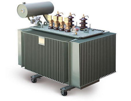
Transformers and converters are key components in AC and DC circuits. In AC systems, transformers use electromagnetic induction to step up or down voltage levels, following the formula Vs/Vp = Ns/Np, where Vs and Vp are the secondary and primary voltages Ns and Np are the number of turns in the secondary and primary coils. In DC systems, converters change voltage levels or convert between AC and DC current power sources using devices like rectifiers and inverters.

Safety implications are paramount when dealing with AC and DC. Both types of electrical current pose potential hazards, including electric shock, burns, and fires. However, AC may be perceived as more dangerous due to its ability to cause muscle contractions, making it difficult to release an electrified object. Regardless, modern safety measures such as grounding, circuit breakers, and fuses have significantly mitigated the risks associated with both types of electrical current.

The unique properties of both currents enable them to serve a wide range of applications, from powering homes and industrial facilities to running delicate electronic devices and renewable energy systems. By grasping the intricacies of voltage, frequency, waveform, conversion, and safety measures, individuals can make informed decisions when choosing between alternating and direct current for specific purposes.

Moreover, the continuing advancements in power transmission technologies, such as direct high-voltage current (HVDC) transmission systems, are bridging the gap between alternating and direct current applications, allowing for more efficient and flexible electricity infrastructure. This progress showcases the importance of understanding both types of electrical currents and their evolving roles in our increasingly interconnected world.

One can explore real-world examples of their use to appreciate the difference between AC and DC further. For example, AC power is harnessed in large-scale power plants, such as coal-fired plants and hydroelectric facilities, which produce electricity using rotating magnets to generate alternating current. In contrast, DC power is often found in batteries, solar panels, and fuel cells, which constantly rely on steady magnetism or chemical reactions to flow electrons.


Related Articles

Related News

Electric Power Systems

Electric power systems manage generation, transmission, and distribution across grids and substations, using protection relays, SCADA, and control systems to ensure reliability, stability, power quality, and efficient load flow with renewable integration.


What Are Electric Power Systems?

Networks that generate, transmit, and distribute power, ensuring reliability, stability, and efficient grid operation.

✅ Includes generation, transmission, distribution, and substations.

✅ Uses protection, SCADA, and controls for reliability and safety.

✅ Integrates renewables with load flow, stability, and demand forecasting.


Electric power systems have evolved significantly in recent years, driven by the increasing demand for clean and sustainable energy sources. Advancements in renewable energy integration, smart grid technology, energy storage, and microgrids are transforming how we generate, transmit, and consume electricity. In addition, as the world continues to face the challenges of climate change and security, developing and implementing these technologies are essential for building a more sustainable and resilient future. Readers new to core concepts can review what electricity is to connect these technologies with fundamental principles.


The main components of an electric power system include generation, transmission and distribution, and load management. Generation refers to producing energy from various sources such as fossil fuels, nuclear and renewable energy. Renewable electrical energy sources, like solar, wind, and hydro, are increasingly being integrated into electric power systems to reduce dependence on fossil fuels and decrease greenhouse gas emissions. However, integrating renewable energy sources requires advanced technologies and strategies to maintain grid stability. For a concise survey of primary resources, see major sources of electricity for additional context on resource mixes. Those interested in the conversion processes can explore how electricity is generated to understand key methods and tradeoffs.

One such technology is the smart grid, an intelligent network that uses digital communication technology to monitor and control the flow of electricity. Smart grids enable better integration of renewable sources by managing their intermittent nature and ensuring grid stability. Additionally, smart grids facilitate demand response, a mechanism that encourages consumers to adjust their consumption based on real-time price signals, ultimately leading to more efficient use of resources. For system-level context on grid architecture, the overview at electricity grid basics explains how modern networks coordinate supply and demand.

Energy storage plays a crucial role, particularly in renewable integration. By storing excess energy generated during periods of low demand, energy storage systems can help balance supply and demand, improve grid stability, and reduce the need for additional generation plants. Some common energy storage technologies include batteries, pumped hydro, and flywheels. For background on production metrics that storage helps smooth, consult electricity production data to see how output varies across time.

Microgrids, small-scale systems that can operate independently or in conjunction with the main grid, contribute to more resilient systems. They often incorporate renewable sources, storage, and advanced control systems to provide a reliable electricity supply, especially during grid outages or emergencies. Microgrids can also reduce losses associated with long-distance electricity transmission and help alleviate stress on the main grid.

Grid stability remains one of the key challenges. The integration of renewable sources and the increasing demand for electricity place significant stress on the existing infrastructure. Solutions for grid stability include advanced control systems, energy storage, and distributed generation. Distributed generation refers to smaller-scale generation units, like solar panels or wind turbines, located closer to the end-users, which can help reduce the burden on the main grid. Engineers use rigorous studies such as power system analysis to evaluate contingencies and design robust operating strategies.

Demand response is managed in modern electric power systems through advanced communication and control technologies. Real-time data on consumption and generation allows utilities to adjust pricing and encourage consumers to shift their usage patterns, helping to reduce peak demand and improve overall system efficiency.

Emerging technologies in electric power systems include single-phase and three-phase power supplies designed to deliver electricity more efficiently and effectively to various types of loads. Single-phase power is typically used in residential settings, while three-phase power is more commonly used in commercial and industrial applications. Innovations in electrical engineering in the United States also drive advancements in transmission and distribution systems, focusing on reducing losses and improving reliability. A broader view of production scaling and plant types is provided in electricity generation overviews that link equipment choices with system performance.


Related Articles

View more

Capacitors in Series Explained

Capacitors in series lower the total capacitance but increase voltage handling. This configuration is widely used in electronics, circuit design, and energy storage to balance voltage and improve reliability.


What are Capacitors in Series?

Capacitors in series describe a circuit configuration where capacitors are connected end to end, affecting capacitance and voltage distribution.

✅ The total capacitance is always less than the smallest capacitor value

✅ Voltage divides across each capacitor based on its capacitance

✅ Improves voltage rating of circuits while lowering equivalent capacitance

They play a critical role in various electronic applications, and understanding their characteristics, advantages, and potential drawbacks is essential for designing and implementing successful circuits. By mastering the concepts of capacitance, voltage distribution, and energy storage, one can leverage capacitors in series to create optimal circuit designs. To fully understand how capacitors (caps) behave in different setups, it helps to compare Capacitance in Parallel with series connections and see how each affects circuit performance.


Capacitors are fundamental components in electronic circuits, and their applications are vast, ranging from simple timing circuits to sophisticated filtering applications. This article delves into the intricacies of caps connected in series, highlighting their characteristics, advantages, and potential drawbacks.

To understand capacitors in series, it's essential first to grasp the concept of capacitance, which represents a capacitor's ability to store electric charge. Caps consist of two conductive plates separated by a dielectric material that can store energy when an applied voltage is present. The amount of energy stored depends on the capacitance value, voltage rating, and the dielectric material used. Engineers often study Capacitance and its capacitance definition to calculate charge storage and predict how components will interact in series circuits. 

When caps are connected in series, their individual capacitance values contribute to the total equivalent capacitance. The series connection is achieved when the positive plate of one capacitor is connected to the negative plate of the subsequent capacitor. This forms a continuous path for current flow, creating a series circuit.

Calculating the total capacitance for capacitors in series is different from parallel capacitors. In a series connection, the reciprocal of the total equivalent capacitance is equal to the sum of the reciprocals of the individual capacitance values. Mathematically, this is represented as:

1/C_total = 1/C1 + 1/C2 + 1/C3 + ... + 1/Cn

Where C_total is the total equivalent capacitance, and C1, C2, C3, ... Cn are the individual capacitance values of the number of caps connected in series.

In a series connection, the electric charge stored in each capacitor is the same. However, the voltage across each capacitor varies depending on its capacitance. According to Kirchhoff's voltage law, the sum of voltages across individual capacitors must equal the applied voltage. Thus, higher capacitance values will have lower voltage drops, while lower capacitance values will have higher voltage drops.

There are both advantages and disadvantages to connecting capacitors in series. On the plus side, the voltage rating of the series connection increases, allowing the circuit to handle higher voltage levels without risking damage to the caps. This feature is particularly useful in high-voltage capacitors in series applications. Alongside capacitors, Amperes Law and Biot Savart Law provide deeper insight into the electromagnetic principles that govern current and voltage distribution.

However, there are also drawbacks to this arrangement. The total equivalent capacitance decreases as more capacitors are added to the series, which may limit the energy storage capabilities of the circuit. Moreover, in the event of a capacitor failure, the entire series connection is compromised.

Different capacitor types and values can be combined in a series configuration, but care must be taken to consider each capacitor's voltage ratings and tolerances. For instance, mixing capacitors with different dielectric materials may lead to uneven voltage distribution and reduced overall performance. Since Capacitors are essential to energy storage and timing circuits, learning their behavior in a Capacitors in Series arrangement is key for advanced electronics design.

Determining the total energy stored in a series connection of caps involves calculating the energy stored in each individual capacitor and then summing those values. The formula for energy storage in a capacitor is:

E = 0.5 * C * V^2

Where E is the energy stored, C is the capacitance, and V is the voltage across the capacitor. Calculating each capacitor's energy and adding the results can determine the total energy stored in the series connection.

Compared with parallel configurations, the total capacitance increases in parallel connections while it decreases in series. In parallel, the total capacitance is the sum of the individual capacitance values:

C_total = C1 + C2 + C3 + ... + Cn

A crucial aspect of working with capacitors in series is charge distribution. As mentioned earlier, the electric charge stored in each capacitor is the same, but the voltage distribution varies depending on the capacitance values. This characteristic influences the circuit's behaviour and must be considered when designing complex electronic systems. Uneven voltage distribution can affect the entire system's performance, making choosing caps with appropriate capacitance values and voltage ratings for a specific application is vital.

Another important factor to consider is the plate area. In general, caps with larger plate areas have higher capacitance values. Therefore, when connecting capacitors in series, it is essential to evaluate how the plate area of each capacitor influences the overall capacitance of the series connection. Understanding these factors will enable engineers and hobbyists to make informed decisions when designing and constructing electronic circuits.

Capacitors in series are versatile and valuable configurations for various electronic applications. By understanding the principles of capacitance, voltage distribution, energy storage, and the influence of dielectric materials, one can harness the full potential of capacitors connected in series. Additionally, being mindful of the advantages and disadvantages of this configuration and considering the compatibility of different capacitor types and values will enable the creation of efficient, reliable, and effective electronic circuits. As electronics evolve, they will remain critical in developing innovative devices and systems. A solid foundation in Basic Electricity makes it easier to grasp why capacitors in series lower overall capacitance but increase voltage handling.


Related Articles


View more

Alternative Electricity Key To Carbon Reduction

Alternative electricity integrates renewable energy, smart grids, and distributed generation, combining solar photovoltaics, wind power, hydropower, and battery storage with power electronics and demand response to decarbonize grids and improve reliability.


What Is Alternative Electricity?

Alternative electricity uses renewables, storage, and smart grids to deliver reliable, low-carbon power.

✅ Power electronics enable PV, wind, and storage grid integration

✅ Smart inverters support voltage, frequency, and reactive power control

✅ Microgrids improve resilience with islanding and load management


Alternative electricity power is essential if we are to find affordable and workable sources of energy before the world completely consumes its limited supply of energy sources. Many countries have started to introduce renewable energy schemes and many countries have invested money into researching and even producing different sources of electricity energy. While it is essential that we become less reliant or not reliant at all on fossil fuels, many forms of alternate energy have their disadvantages as well as their obvious advantages. The advantages of alternate energy far outweigh the disadvantages. For a primer on how modern grids convert primary energy into usable power, see this overview of how electricity is generated across different technologies today.


Wind Energy

Harnessing the power of the wind and using it to our ends is hardly a new idea. Windmills have been and still are used for many different purposes and have been for a great many years, but the improvement of turbines combined with the improved technology to turn the motion of turbine blades into an energy source has seen a marked increase in the use of electricity generating turbines. Detailed diagrams explain how turbine blades capture kinetic energy to generate electricity efficiently under varying wind speeds.

Wind power is very popular, but in order to provide a reasonable amount of power it may prove necessary to have large amounts of turbines. On windy days, and even not so windy days some turbines make a noise that many residents consider to be unbearable. Areas of open countryside are protected by conservation orders, which means they can’t be built there either and if there is no conservation order there are still protestors willing to do almost anything to stop the turbines being built. The only viable option left is to use offshore wind farms and these are being investigated, developed and planned all around the world but it takes too many turbines to create a reasonable amount of power and eventually they will have to be built inland; a matter that will be contested wherever the wind farms are proposed to be built.

Understanding capacity factors and grid integration is key to planning electricity production that balances reliability and community impacts.

Wind power is produced by converting wind energy into electricity. Electricity generation from wind has increased significantly in the United States since 1970. Wind power provided almost 5% of U.S. electricity generation in 2015. These trends mirror broader shifts in electricity generation portfolios as states pursue renewable portfolio standards.


Solar Energy

Solar energy is probably the most common form of alternate energy for everyday people and you can see solar lights ad other solar accessories in many gardens. Governments are beginning to offer grants to assist in paying for photovoltaic roof tiles; these tiles are easily fitted onto your roof and collect the heat from the sun. This heat can either be used to heat water or can even be converted into energy electric power. The advantage for the consumer is that by including a grid tie system you can actually sell unused energy back to the grid. Photovoltaic tiles take the place of ordinary roof tiles and can be perfectly blended to fit the look of the outside of your house. With solar energy you too can help the environment.

Many utilities now offer tariffs that credit exports from rooftop systems, linking household budgets to green electricity choices in a transparent way.

Solar power is derived from energy from the sun. Photovoltaic (PV) and solar-thermal electric are the two main types of technologies used to convert solar energy to electricity. PV conversion produces electricity directly from sunlight in a photovoltaic (solar) cell. Solar-thermal electric generators concentrate solar energy to heat a fluid and produce steam to drive turbines. In 2015, nearly 1% of U.S. electricity generation came from solar power. PV and solar-thermal now sit alongside other major sources of electricity in utility planning models.


Biomass

Ask most people which renewable energy source is the most widely used and they would say either wind or solar, but they’d be wrong or at least they certainly would in America. Since 2000 Biomass has been the most highly produced alternate energy in the United States. Using plant and animal material to create energy isn’t without its downfalls. It would almost certainly meet with competition from residents if biomass power stations were to be created in built up areas. The decomposing plants and animal waste creates an awful smell that is incredibly difficult to mask but it is very renewable (there’s always plants and animal waste).

Biomass is material derived from plants or animals and includes lumber and paper mill wastes, food scraps, grass, leaves, paper, and wood in municipal solid waste (garbage). Biomass is also derived from forestry and agricultural residues such as wood chips, corn cobs, and wheat straw. These materials can be burned directly in steam-electric power plants, or they can be converted to a gas that can be burned in steam generators, gas turbines, or internal combustion engine-generators. Biomass accounted for about 2% of the electricity generated in the United States in 2015.


Other renewable energy sources

These are the main three renewable energy sources that the countries of the world are creating at the moment but there are others. Whether nuclear power is a viable alternate or not is a debate that will undoubtedly rage on forever, but it is a renewable energy and some countries already have extensive capabilities to produce it. Modern technology means that nuclear power stations are safer than they’ve ever been and damage to people, animals or plantation is highly unlikely. However, it takes a long time to develop nuclear power station and even plants that are already being built may take ten years to come to fruition.


Renewable energy sources provide 13% of U.S. electricity

Hydropower, the source of about 6% of U.S. electricity generation in 2015, is a process in which flowing water is used to spin a turbine connected to a generator. Most hydropower is produced at large facilities built by the federal government, like the Grand Coulee Dam. The West has many of the largest hydroelectric dams, but there are many hydropower facilities operating all around the country. For a deeper look at how turbines and dams convert flow into water electricity, engineers often study case histories from multiple river systems.

Hydro power is used in some countries and uses the motion of waves to create energy. While it is a possibility, the amount of energy produced is minimal and the outlay to set these schemes up is quite large. Without further investigation and improvement in the techniques used it is unlikely that Hydropower will become a major player in the renewable energy world.

Geothermal power comes from heat energy buried beneath the surface of the earth. In some areas of the United States, enough heat rises close enough to the surface of the earth to heat underground water into steam, which can be tapped for use at steam-turbine plants. Geothermal power generated less than 1% of the electricity in the United States in 2015.


Related Articles

View more

Free Electricity Explained

Free electricity is power generated without fuel costs, typically from solar or wind sources. After setup, systems like solar panels can reduce or eliminate bills through net metering, helping promote sustainability and energy independence for homes and businesses.


What is Free Electricity?

Free electricity refers to energy that costs nothing to generate after initial setup, typically utilizing natural sources.

✅ Harnesses renewable energy sources like solar panels and wind turbines

✅ Reduces or eliminates long-term electricity costs

✅ Promotes sustainable and eco-friendly living solutions


The Reality of Free Electricity

True “free electricity” does not exist in the sense of unlimited, no-cost power available without investment. However, generating your electricity at home through solar panels or small wind systems can reduce your reliance on the power grid and lower your energy bills significantly, sometimes to zero. This cost reduction is what many people mean when they refer to "free electricity."

Purchasing and installing a solar power system is not free, but it pays off over time. It’s a long-term investment that benefits both the environment and your finances. Some homeowners even reach the point where their solar systems generate more electricity than they use.

In such cases, through a policy known as net metering, these homeowners can send excess electricity back to the power grid and receive compensation from their utility company.


What is Net Metering?

Net metering is a billing arrangement that allows consumers who generate their own electricity to send excess power back to the grid and receive credit for it. Here’s how it works:

  • Net metering allows you to sell the electricity produced by a solar system on your home back to the electric power grid.

  • Net Metering occurs when your meter spins backwards as solar electricity is being produced, storing the excess energy on the grid.

  • Once energy is actually being consumed, your meter spins forward to collect the energy that has been saved on your electric power grid.

  • For the energy that you do not consume, the electric utility will compensate you. If you get paid enough money from the electricity that you don't use and sell to them, then that profit can be used to pay for your existing consumption, making it essentially free electricity.

Some utilities offer cash payments for the surplus, while others provide energy credits that reduce your bill. Either way, your electricity costs can be significantly reduced—and in some cases, essentially eliminated.


Key Considerations for a Free Electricity System

A few things to watch out for when choosing to invest in a Free Electricity solar power system.

  • You must conserve your energy consumption to ensure that you don't exceed the amount of solar energy produced.

  • By exceeding the amount of power generated many times for the grid or saved, you are then charged regular rates for electricity provided by your electric utility.

  • You must watch your solar energy production. Keep track of the daily energy production of your system.

  • Check your utility bill each month to ensure that you are credited or reimbursed for any and all extra energy generated.

  • To control your electricity usage, consider using a time-of-use electric meter to further capitalize on your investment.


Utility Policies Vary

Not all utility companies offer generous net metering. Some may only provide energy credits, while others pay wholesale rates for your excess electricity. It's essential to check with your local utility to understand how they handle customer-generated power.

While the term “free electricity” is somewhat misleading, it does accurately reflect the very real possibility of generating low-cost or no-cost power after your initial system is installed. Through renewable energy systems and programs like net metering, homeowners can reduce or eliminate energy bills and make a lasting contribution to a cleaner, more sustainable future.


Related Articles


View more

Watthour Meter Explained

A watthour meter measures electrical energy consumption in kilowatt-hours (kWh) for residential, commercial, and industrial applications, ensuring accurate billing, energy management, and compliance with utility standards.


What is a Watthour Meter?

✅ Measures total electrical energy in kilowatt-hours (kWh) over time

✅ Supports accurate billing, energy monitoring, and demand analysis

✅ Used in residential, commercial, and industrial revenue metering


Advancements in Watthour Meter Technology and Energy Measurement

Watthour meter technology plays a crucial role in modern electrical engineering and maintenance by providing accurate measurement and monitoring of energy consumption. These devices are indispensable for managing energy efficiency, optimizing power distribution, and ensuring compliance with regulatory standards. For electrical professionals, understanding how they operate and are maintained is essential to minimize energy losses and enhance the reliability of electrical systems. With the growing demand for precise energy data in both residential and industrial applications, staying informed about advancements in watthour meter technology is more important than ever. Understanding how a watthour is calculated helps clarify how a watthour meter tracks total energy usage for accurate billing. 


How Induction Type Single Phase Watt Hour Meters Work

Induction type meters, commonly used as single phase watt hour meters, provide accurate measurement of electrical energy consumption in residential and small commercial installations.

Your electric utility is not too interested in how much power you're consuming for one ap­pliance or even how much power a single household is drawing at any given time. By far the greater concern is the total energy that is used over a day, a week, a month or a year. Electrical energy is measured in watt-hours or, more commonly for utility pur­poses, in kilowatt-hours (kWh). The device that measures this consumption is the watt-hour meter or kilowatt-hour meter. For a deeper understanding of the units used in metering, see our guide on electrical energy and how it is measured in kilowatt-hours.

The most common method for measuring electrical energy is by using a small elec­tric motor device, whose speed depends on the current, and thereby on the power at a constant voltage. The number of turns of the motor shaft, in a given length of time, is di­rectly proportional to the number of watt hours consumed. The motor is placed at the point where the utility wires enter the house, apartment or building. This is usually at a point where the voltage is 234 V. This is split into some circuits with 234 V, for heavy-duty appliances such as the oven, washer and dryer, and the general household circuits for lamps, clock radios and television sets. The principles behind watthour meters are closely tied to basic electricity and the relationship between active power and time.


Understanding the Spinning Disk in Electromechanical Watthour Meters

You've surely seen the little disk in the utility meter going around and around, sometimes fast, other times slowly. Its speed depends on the power you're using. The total number of turns of this little disk, every month, determines the size of the bill you will get, as a function also, of course, of the cost per kilowatt hour for electricity.

Kilo-watt-hour meters count the number of disk turns by means of geared, rotary drums or pointers. The drum-type meter gives a direct digital readout. The pointer type has several scales calibrated from 0 to 9 in circles, some going clockwise and others go­ing counterclockwise. Mechanical and electronic meters both rely on the concepts of electrical resistance and current to provide precise readings.


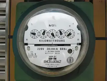
How to Read a Pointer-Type Watthour Meter Accurately

Reading a pointer-type utility meter is a little tricky because you must think in whatever direction (clockwise or counterclockwise) the scale goes. An example of a pointer-type utility meter is shown in Fig. 3-11. Read from left to right. For each little meter, take down the number that the pointer has most recently passed. Write down the rest as you go. The meter in the figure reads 3875 kWh. If you want to be really pre­cise, you can say it reads 3875-1/2 kWh. To place watt hour metering in historical context, explore our history of electricity page and learn how early meters evolved into today’s advanced devices.


Fig. 3-11 An example of a utility kilo-watthour meter. The reading is a little more than 3875 kWh.


Related Articles


View more

Equivalent Resistance

Equivalent resistance is the total resistance of a circuit that simplifies multiple resistors into a single resistor. It is calculated differently for series and parallel circuits, helping determine current flow, voltage distribution, and overall power consumption in electrical networks.


What is Equivalent Resistance?

Equivalent resistance is a crucial concept for individuals working with electrical circuits. It: 

✅ Represents the single resistance that replaces multiple resistors in a circuit.

✅ Simplifies calculations of current, voltage, and power.

✅ Found using series or parallel formulas based on resistor arrangement.

By mastering the calculation methods for series and parallel circuits, understanding the relationship with Ohm's law, and applying Kirchhoff's laws in more complex situations, you can efficiently analyze and design electrical systems that meet the requirements of various applications. Furthermore, by incorporating equivalent resistance calculations into your skillset, you'll be better prepared to tackle the exciting challenges presented by the ever-evolving world of electronics and power systems.


Equivalent Resistance in Series vs. Parallel Circuits

Configuration Formula Key Characteristics Example Calculation
Series R_eq = R1 + R2 + R3... Same current flows through all resistors; total resistance increases; voltage drop varies across components. For R1=4Ω, R2=6Ω: R_eq = 4Ω + 6Ω = 10Ω
Parallel 1/R_eq = 1/R1 + 1/R2 + 1/R3... Same voltage across each resistor; total resistance decreases; current divides among paths. For R1=4Ω, R2=6Ω: 1/R_eq = 1/4 + 1/6 = 0.416 → R_eq ≈ 2.4Ω

To calculate the equivalent resistance of a network, it is often necessary to determine the sum of the individual resistances. This involves adding the resistance values of each individual resistor in the network, providing a baseline for further calculations. This is a resistance formula for a single resistor, as well as for calculating resistors connected in parallel or in series.

Electrical resistance (R) is a measure of the opposition to the flow of electric current within a circuit. It is determined by the material and dimensions of the conductor, as well as the temperature and other environmental factors. It is measured in ohms (Ω), with lower R indicating greater conductivity and vice versa.


Equivalent Resistance Formula

When a group of resistors is connected end-to-end, they form a series. In a series circuit, the total resistance is equal to the sum of the individual Rs, as current must flow through each resistor in turn. The equivalent resistance of a series circuit is calculated by adding the values of each individual resistor:

Req = R1 + R2 + R3 + ...

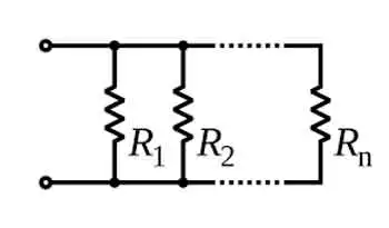
Resistors connected across the same potential difference, or applied voltage, are referred to as being connected in parallel. In a parallel circuit, the total R is less than the R of any individual resistor as the current divides among the resistors. The equivalent resistance of a parallel circuit is calculated using the reciprocal formula:

1/Req = 1/R1 + 1/R2 + 1/R3 + ...

Equivalent resistance is the single R value that can replace a group of resistors in a circuit, offering the same overall R. This simplifies circuit analysis and allows for more straightforward calculations of current and voltage values.

Ohm's law is an essential principle in electronics and relates closely to equivalent resistance. Ohm's law states that the current (I) flowing through a resistor is directly proportional to the applied voltage (V) and inversely proportional to the R. The equation is:

V = IR

By calculating equivalent resistance for a given circuit, we can use Ohm's law to determine the overall current flowing through the circuit and the voltage drops across each resistor.


Series and parallel circuits exhibit different properties when it comes to equivalent resistance. In series circuits, the overall R increases with the addition of more resistors, which means the total current will decrease. In parallel circuits, adding more resistors results in a decrease in total resistance, causing an increase in total current. Understanding these differences is crucial for designing circuits that meet specific electrical requirements.


Kirchhoff's Law

Kirchhoff's laws are another essential tool for calculating equivalent resistance in more complex circuits that cannot be simplified as purely series or parallel. Kirchhoff's current law (KCL) states that the sum of currents entering a junction in a circuit must equal the sum of currents leaving the junction. Kirchhoff's voltage law (KVL) asserts that the sum of the voltages around any closed loop in a circuit must equal zero. By applying these laws, we can create a system of equations to solve for unknown resistance values in a network, ultimately determining the equivalent resistance.


Real-World Applications

Real-world applications of equivalent resistance can be found in various fields, such as electronics, power distribution, and telecommunications. For example, various components have different R values in electronic devices, such as smartphones. Calculating the equivalent resistance enables engineers to design efficient power management systems, ensuring optimal performance and extended battery life. In power distribution networks, equivalent resistance calculations are essential for determining voltage drops and current values across transmission lines, enabling the design of efficient and reliable power delivery systems.

Understanding equivalent resistance is vital for professionals and students who deal with electrical circuits. From simplifying complex networks to designing efficient circuits, equivalent resistance plays a central role in analyzing and developing modern electronic systems. Familiarity with this concept and associated principles like Ohm's law and Kirchhoff's laws ensures a strong foundation for anyone working with electronics, power systems, and telecommunications.


Technology Advances

As technology advances, the importance of equivalent resistance in designing and analyzing new devices and systems will only grow. Calculating and understanding equivalent resistance enables engineers to push the boundaries of innovation and improve upon existing systems, resulting in more efficient, high-performance solutions for consumers and industries alike.

To further develop your understanding of equivalent resistance and related concepts, consider exploring the wealth of educational resources available online and in textbooks, as well as seeking hands-on experience through workshops or real-world projects. Applying this knowledge to practical scenarios will enable you to tackle various electrical and electronic challenges.

Related Articles


View more

Sign Up for Electricity Forum’s Newsletter

Stay informed with our FREE Newsletter — get the latest news, breakthrough technologies, and expert insights, delivered straight to your inbox.

Electricity Today T&D Magazine Subscribe for FREE

Stay informed with the latest T&D policies and technologies.
  • Timely insights from industry experts
  • Practical solutions T&D engineers
  • Free access to every issue

Live Online & In-person Group Training

Advantages To Instructor-Led Training – Instructor-Led Course, Customized Training, Multiple Locations, Economical, CEU Credits, Course Discounts.

Request For Quotation

Whether you would prefer Live Online or In-Person instruction, our electrical training courses can be tailored to meet your company's specific requirements and delivered to your employees in one location or at various locations.