Harmonic Distortion


Harmonic Distortion explained

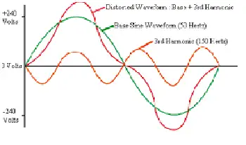
Harmonic distortion is the deviation from the ideal electrical waveform caused by nonlinear loads. It impacts power quality, increases heat in equipment, and can lead to system inefficiencies. Monitoring and mitigation are essential in industrial electrical systems.


What is Harmonic Distortion?

Harmonic distortion is not a new phenomenon in power systems. Concern over distortion has fluctuated several times throughout the history of AC electric power systems.

✅ Reduces overall power quality and system reliability

✅ Can damage equipment and increase heat generation

✅ Requires monitoring to ensure system efficiency and safety

In the 1930s and 1940s, the primary sources were transformers, with the primary problem being inductive interference with open-wire telephone systems. Early arc lighting caused similar concern due to its harmonic content, just as today’s electronic power converters do.

Today, nonlinear devices like variable frequency drives (VFDs), arc furnaces, computer power supplies, and LED lighting introduce significant harmonic distortion into electrical systems. Nonlinear devices do not draw current in a linear relationship to voltage, which distorts the sinusoidal waveform and introduces harmonic currents. Harmonic distortion is one of the many issues covered in our comprehensive Power Quality resource channel, which explores causes, effects, and solutions.


Why It Matters

  • Harmonics degrade power quality

  • Increase energy losses and heat in conductors and transformers

  • Lead to premature failure of motors and sensitive electronics

  • Interfere with communication lines

In contrast, voltage sags and interruptions are nearly universal to every feeder and represent the most numerous and significant power quality deviations. The end-user sector suffers more from harmonic problems than the utility sector. Industrial users with adjustable speed drives, arc furnaces, induction furnaces, and similar equipment are significantly more susceptible to problems caused by harmonic distortion. To understand the relationship between harmonics and apparent energy flow, see our explanation of Apparent Power vs Real Power.

A good assumption for most utilities in the United States is that the sine wave voltage generated in central power stations is very good. In most areas, the voltage found on transmission systems typically has much less than 1% distortion. However, the distortion increases as the load approaches. At some loads, the current waveforms barely resemble a sine wave. Electronic power converters can chop the current into seemingly arbitrary waveforms. Managing nonlinear loads often requires Power Factor Correction to reduce harmonic effects and improve efficiency.


Industry Standards

  • IEEE 519: Sets recommended harmonic limits for both voltage and current.

  • IEC 61000-4-7: Defines methods of measuring harmonics and interharmonics.


Harmonic Distortion and Nonlinear Devices

Harmonic distortion is caused by nonlinear devices in the power system. A nonlinear device is one in which the current is not proportional to the applied voltage. Figure 1 illustrates this concept using the case of a sinusoidal voltage applied to a simple nonlinear resistor, where the voltage and current vary according to the curve shown. While the applied voltage is perfectly sinusoidal, the resulting current is distorted. Increasing the voltage by a few percent may cause the current to double and exhibit a different waveform. You can calculate your system’s power quality impact using our Apparent Power Calculator for precise performance metrics.

This is the source of most harmonic distortion in a power system. Figure 1 illustrates that any periodic, distorted waveform can be expressed as a sum of sinusoids. When a waveform is ideal from one cycle to the next, it can be represented as a sum of pure sine waves in which the frequency of each sinusoid is an integer multiple of the fundamental frequency of the distorted wave. This multiple is called a harmonic of the fundamental, hence the name of this subject matter. The sum of sinusoids is referred to as a Fourier series, named after the great mathematician who discovered the concept. Nonlinear loads like VFDs and arc furnaces can affect grounding; learn more in our guide to Electrical Grounding.


Fig. 1. Current distortion caused by nonlinear resistance


Voltage and Current Distortion

The term "harmonics" is often used by itself without further qualification. Generally, it could mean one of the following three:

  1. The harmonic voltages are too great (the voltage is too distorted) for the control to properly determine firing angles.

  2. The harmonic currents are too great for the capacity of some devices in the power supply system, such as transformers, and the machine must be operated at a lower than rated power.

  3. The harmonic voltages are too great because the harmonic currents produced by the device are too great for the given system condition.

Clearly, there are separate causes and effects for voltages and currents, as well as some relationship between them. Thus, the term harmonics by itself is inadequate to describe a problem definitively. Nonlinear loads appear to be sources of harmonic current, injecting harmonic currents into the power system. For nearly all analyses, it is sufficient to treat these harmonic-producing loads simply as current sources. There are exceptions to this as described later.


Fig 2. Harmonic currents flowing through the system impedance result in harmonic voltages at the load.

Voltage distortion is the result of distorted currents passing through the linear, series impedance of the power delivery system, as illustrated in Fig. 2. Although assuming that the source bus is ultimately a pure sinusoid, there is a nonlinear load that draws a distorted current. The harmonic currents passing through the system's impedance cause a voltage drop for each harmonic. This results in voltage harmonics appearing at the load bus. The amount of voltage distortion depends on the impedance and the current. Assuming the load bus distortion stays within reasonable limits (e.g., less than 5%), the amount of harmonic current produced by the load is generally constant.

While the load current harmonics ultimately cause voltage distortion, it is worth noting that the load has no control over the voltage distortion. The same load put in two different locations on the power system will result in two different voltage distortion values. Recognition of this fact is the basis for the division of responsibilities for harmonic control that is found in standards such as IEEE Std 519-1992.

  • Control over the amount of harmonic current injected into the system occurs at the end-use application.

  • Assuming the harmonic current injection is within reasonable limits, the control over voltage distortion is exercised by the entity that controls the system impedance, typically the utility.

One must be careful when describing harmonic distortion phenomena, as there are distinct differences between the causes and effects of harmonic voltages and currents. The use of the term harmonics should be qualified accordingly. By popular convention in the power industry, the term is used by itself most of the time when referring to load apparatus, indicating that the speaker is referring to the harmonic currents. When referring to the utility system, the voltages are generally the subject. For systems affected by harmonic-induced overheating, understanding Capacitor Bank applications is essential for voltage support and harmonic filtering. For in-depth harmonic analysis, explore our guide to using a Power Quality Analyzer to identify waveform distortion and power anomalies.


Related Articles


Related News

Capacitance Explained

Capacitance: Understanding the Ability to Store Electricity

Capacitance is an essential concept in electrical circuits, and it describes the ability of a capacitor to store electrical energy. Capacitors are electronic components used in many circuits to perform various functions, such as filtering, timing, and power conversion. Capacitance is a measure of a capacitor's ability to store electrical energy, and it plays a crucial role in the design and operation of electrical circuits. This article provides an overview of capacitance, including its definition, SI unit, and the difference between capacitor and capacitance.


What is Capacitance?

Capacitance is the ability of a capacitor to store electrical charge. A capacitor consists of two conductive plates separated by a dielectric material. The conductive plates are connected to an electrical circuit, and the dielectric material is placed between them to prevent direct contact. When a voltage source is applied to the plates, electrical charge builds up on the surface of the plates. The amount of charge that a capacitor can store is determined by its capacitance, which depends on the size and distance between the plates, as well as the dielectric constant of the material.

The energy storing capability of a capacitor is based on its capacitance. This means that a capacitor with a higher capacitance can store more energy than a capacitor with a lower capacitance. The energy stored in a capacitor is given by the formula:

Energy (Joules) = 0.5 x Capacitance (Farads) x Voltage^2

The ability to store energy is essential for many applications, including filtering, timing, and power conversion. Capacitors are commonly used in DC circuits to smooth out voltage fluctuations and prevent noise. They are also used in AC circuits to filter out high-frequency signals.


What is Capacitance and the SI Unit of Capacitance?

Capacitance is defined as the ratio of the electrical charge stored on a capacitor to the voltage applied to it. The SI unit of capacitance is the Farad (F), which is defined as the amount of capacitance that stores one coulomb of electrical charge when a voltage of one volt is applied. One Farad is a relatively large unit of capacitance, and most capacitors have values that are much smaller. Therefore, capacitors are often measured in microfarads (µF) or picofarads (pF).

The capacitance of a capacitor depends on several factors, including the distance between the plates, the surface area of the plates, and the dielectric constant of the material between the plates. The dielectric constant is a measure of the ability of the material to store electrical energy, and it affects the capacitance of the capacitor. The higher the dielectric constant of the material, the higher the capacitance of the capacitor.


What is the Difference Between Capacitor and Capacitance?

Capacitor and capacitance are related concepts but are not the same thing. Capacitance is the ability of a capacitor to store electrical energy, while a capacitor is an electronic component that stores electrical charge. A capacitor consists of two conductive plates separated by a dielectric material, and it is designed to store electrical charge. Capacitance is a property of a capacitor, and it determines the amount of electrical charge that the capacitor can store. Capacitance is measured in Farads, while the capacitor is measured in units of capacitance, such as microfarads (µF) or picofarads (pF).


What is an Example of Capacitance?

One example of capacitance is a common electronic component known as an electrolytic capacitor. These capacitors are used in a wide range of electronic circuits to store electrical energy, filter out noise, and regulate voltage. They consist of two conductive plates separated by a dielectric material, which is usually an electrolyte. The electrolyte allows for a high capacitance, which means that these capacitors can store a large amount of electrical energy.

Another example of capacitance is the human body. Although the capacitance of the human body is relatively small, it can still store a significant amount of electrical charge. This is why people can sometimes feel a shock when they touch a grounded object, such as a metal doorknob or a handrail. The capacitance of the human body is affected by several factors, including the size and shape of the body, as well as the material and proximity of the objects it comes into contact with.

View more

Understanding Ground Electricity

Ground electricity underpins grounding and earthing practices, managing earth potential and fault current. It ensures equipotential bonding, surge protection, and safety compliance per IEC/NEC standards for power systems, electronics, and lightning protection.


What Is Ground Electricity?

Ground electricity is the earth reference and return path that stabilizes systems and safely carries fault current.

✅ Provides low-impedance fault current paths to trip protection

✅ Uses earth electrodes, bonding, and grounding conductors

✅ Reduces touch voltage, EMI, and lightning surge damage


Understanding Ground Electricity 

Ground Electricity is a general term that is often used loosely to refer to “Bonding” (Safety Grounding) and “Earth Grounding”.  Personnel of major industries have often misinterpreted grounding to mean that anything in contact with the earth is considered to be grounded. For foundational context, see our overview on how electricity works to understand why grounding concepts are sometimes conflated.

Electrical Grounding is the reference zero for the electrical system.  When we talk about 120 Volts RMS, it represents 120 units above the zero electrical reference.  In residential settings, this reference is commonly tied to service equipment, as explained in our guide to home electricity and typical distribution practices.

Electrical Grounding is the reference zero for the electrical system and all the equipment should be at this same equipment potential plane. Maintaining that equipotential plane is central to electricity safety because it minimizes touch voltage hazards.

According to accident reports, most electrical accidents occur when the earth is used as the safety grounding system (Bonding).   These incidents underscore the broader dangers of electricity when protective paths are improperly designed.

Accident reports details the hazards of using earth as a safety grounding and the practice of electrical grounding the equipment through local grounds. (grounding each individual piece of equipment with a separate ground rod, driven into the earth).  Improper local grounds can also complicate fault clearing during a system electrical fault, increasing damage and downtime.

The best method for ensuring the safety of personnel is to use a “Bonding Conductor”. This conductor should be continuous, with sufficient ampacity and the lowest impedance path back to the circuit interrupting devices, which insures positive operation of the protective devices. A robust bonding network ensures rapid clearing of a ground fault by providing a low-impedance return path for protective devices.

Once a system that connects all the metallic frames of electrical equipment together has been established, then the grounding system must be placed at “Zero Reference Potential”.  The earth grounding electrode should have the lowest resistance value possible, preferably 5 ohms or less.   Coordinating equipment bonding with proper transformer grounding helps maintain stable reference potential across the installation.

This low resistance to earth ground electricity will limit the potential of the electrical system to earth (limiting the stresses placed on components such as switches, insulators and transformers).

It will also reduce the effects of static charges on the electrical system and will protect against lightning strokes, lightning induced voltages, and minimizes the effects of transient over-voltages.

Visit Our Electrical Grounding and Bonding Course 


Related Articles

View more

Total Impedance Calculator

Total impedance calculator determines total opposition in AC circuits by combining resistance, inductive reactance, and capacitive reactance. Input R, L, C, and frequency to find Z in ohms for accurate analysis in power distribution, filters, or signal systems.


Quick Definition: Total Impedance Calculator

  • Purpose: Calculates total opposition (impedance) in AC circuits by combining resistance and reactance.

  • Functionality: Processes inputs like resistance (R), inductance (L), capacitance (C), and frequency to compute impedance (Z).​

  • Applications: Used in designing power supplies, signal transmission systems, and optimizing filter performance.​


A total impedance calculator helps you quickly determine the combined impedance of resistors, inductors, and capacitors in AC circuits. By inputting values for resistance (R), inductive reactance (XL), and capacitive reactance (XC), you can calculate total impedance (Z) for both series and parallel configurations, making circuit analysis faster, more accurate, and easier to understand. A total impedance calculator is a powerful tool used by electrical engineers, technicians, and students to determine the impedance in RLC circuits, whether in series or parallel. These calculators simplify complex calculations involving resistance, inductance, and capacitance by processing formulas that would otherwise require manual computation with complex numbers.

Whether you are designing a power supply, analyzing signal transmission, or optimizing filter performance, a total impedance calculator helps ensure accuracy and efficiency. It is especially valuable when analyzing the behaviour of AC circuits across different frequency ranges in hertz.


What Is Total Impedance?

Total impedance refers to the combined opposition that a circuit presents to the flow of alternating current. It takes into account both resistance (R) and reactance (X), expressed as a single value in ohm (Ω). The two primary types of reactance are:

  • Inductive reactance (caused by coils or inductors)

  • Capacitive reactance (caused by capacitors)

These values change depending on the circuit's frequency, making tools like a total impedance calculator essential for real-time circuit analysis.


Who Uses a Total Impedance Calculator?

  • Electrical engineers use it in power systems, communications, and control circuits.

  • Technicians rely on it to verify component ratings and troubleshoot systems.

  • Educators and students apply it in academic settings for lab work and theoretical analysis.

  • Industrial maintenance professionals use it to evaluate equipment behavior under various loads.

It is particularly helpful when working with an RLC circuit impedance calculation where both inductance (L) and capacitance (C) are present.


What Does a Total Impedance Calculator Do?

A good impedance calculator lets you:

  • Enter known values like resistance (R), inductance L and capacitance C, and frequency in hertz.

  • Automatically compute impedance for either series RLC circuit or parallel RLC circuit setups.

  • Show results using the correct impedance formula, including both magnitude and phase.

  • Factor in angular frequency in rad, derived from ω=2πf\omega = 2\pi fω=2πf, where fff is frequency.

  • Solve expressions like 1ωC\frac{1}{\omega C}ωC1​ or frac 1 omega, commonly used in capacitive reactance calculations.

The result is a fast, accurate way to determine the impedance and analyze AC circuit behavior.


Key Concepts Behind the Calculator


1. Impedance Formula (Z)

This requires working with complex numbers to calculate both magnitude and phase angle.


2. Reactance Components

  • Inductor and capacitor components contribute to the reactive part of the impedance.

  • Capacitive reactance

  • Inductive reactance

These values vary with frequency and affect circuit resonance and behavior.


Why Use a Total Impedance Calculator?

Without a calculator, these formulas can be tedious to evaluate manually—especially when working in real time or across wide frequency in hertz ranges. A calculator ensures:

  • Greater accuracy in design and testing

  • Time-saving analysis for troubleshooting

  • Safer decision-making for load balancing and component selection

In power electronics, knowing the rlc circuit impedance helps prevent equipment damage and improves system efficiency.

A total impedance calculator is an essential tool for modern electrical work. It brings together the core principles of AC circuit analysis—resistance, inductance, capacitance, and frequency—into one user-friendly interface. Whether you're designing systems, teaching students, or maintaining equipment, using this tool helps you quickly and reliably calculate the impedance and make informed decisions.


Related Articles


View more

Nominal Voltage and AC and DC Standards

Nominal voltage is the standard voltage level assigned to electrical equipment or systems for identification. It helps ensure compatibility, performance, and safety across devices without indicating actual operating voltage, which may vary slightly.


What is Nominal Voltage?

Nominal voltage refers to the labelled voltage value of an electrical system or device.

✅ Represents standard system voltage, not an  exact measurement

✅ Helps match equipment compatibility and safety standards

✅ Common in power distribution, residential, and industrial systems


Nominal voltage (NV) is a vital aspect of electrical systems, serving as a reference point for designing, manufacturing, and testing equipment. Additionally, it affects the performance, efficiency, and safety of electrical systems, with voltage regulation ensuring that voltage levels (V) remain within acceptable tolerances. Understanding the differences between nominal voltage, operating voltage (OV), and rated voltage (RV) is crucial for professionals and enthusiasts to ensure the effective operation and maintenance of electrical systems. To better understand how nominal voltage fits within broader system design, see our comprehensive overview on voltage.

It is vital to understand the definition and importance of nominal voltage in electrical systems. NV refers to the standard voltage value assigned to an electrical system, typically the voltage that electrical equipment is designed to operate under normal conditions. This value is crucial because it serves as a reference point for designing, manufacturing, and testing electrical equipment to ensure satisfactory performance. Maintaining voltage stability is essential—learn how voltage drop impacts performance and how to accurately calculate it.

Determining nominal voltage for electrical systems involves considering factors such as the type of equipment being used, the overall power requirements, and the voltage standards set by industry organizations. In some cases, the NV is set by the equipment manufacturer, while in others, it depends on the power grid's Voltage levels. Standard nominal voltages have been established to streamline equipment design and manufacturing processes. Use our voltage drop calculator to determine how wiring distance and load affect nominal voltage in real applications.

The terms NV, OV, and RV often appear in discussions about electrical systems. While they may seem interchangeable, each has a distinct meaning. As previously mentioned, nominal voltage is the standard voltage value designated for an electrical system. On the other hand, OV is the actual voltage at which equipment functions during operation. Similar to nominal voltage, RV refers to the maximum voltage at which equipment can operate continuously without sustaining damage. See how voltage regulators are used to maintain nominal levels and protect sensitive equipment.

Nominal voltage has a direct impact on the performance of electrical systems. Equipment designed for specific NVs operates safely within a particular voltage range. Operating outside this range can result in equipment damage, decreased efficiency, and even electrical fires. Therefore, it is essential to maintain the voltage levels as close as possible to the NV. Our guide to what is voltage explains the differences between nominal, operating, and actual voltage in power systems.

Electrical systems worldwide adhere to common national voltage (NV) standards for alternating (AC) and direct (DC) systems. For AC systems, NV  ranges include 110V, 220V, and 380V, while DC systems typically have NVs of 12V, 24V, or 48V. These standardized voltage levels enable the compatibility and interoperability of electrical equipment across various regions and industries. Learn how wattmeters and voltmeter tools help monitor nominal and real-time voltage values in field diagnostics.

Voltage regulation plays a critical role in controlling an electrical system's output voltage to ensure it remains within the acceptable voltage tolerance. Voltage regulation can be achieved through various means, including transformers, voltage regulators, and software algorithms in modern power systems. By maintaining NV, the electrical system The voltages more efficiently and safely, ensuring the longevity of the equipment.

The voltage tolerance is the range of voltage deviation from the nominal voltage value within which equipment can still operate effectively and safely. Different electrical systems have different voltage tolerances depending on the nature of the equipment and its intended use. For instance, a residential electrical system may have a voltage tolerance of +/- 5%, while an industrial system might tolerate a deviation of +/- 10%. Maintaining the acceptable V tolerance is crucial for the satisfactory operation of electrical equipment.


Nominal Voltage (NV) vs Operating Voltage (OV)

Nominal voltage and OV are two related yet distinct concepts in electrical engineering systems. Understanding the different essentials to ensure electrical systems' safe and efficient operation.

Nominal voltage refers to the standard or reference voltage level assigned to an electrical system, circuit, or device. It is the ideal voltage at which the equipment is designed to operate under normal conditions. NV is a baseline value that allows manufacturers, engineers, and technicians to design, test, and rate electrical equipment consistently.

Conversely, OV is the actual voltage level at which a particular electrical system, circuit, or device is functioning during real-time operation. Unlike nominal voltage, OV can fluctuate due to factors such as load changes, temperature variations, and power supply issues. Although electrical equipment is designed to operate optimally within a specified voltage range around the nominal voltage, slight variations in the operating V are often unavoidable.

In essence, NV serves as the benchmark or target voltage level, while OV reflects the real-world voltage conditions experienced by the electrical equipment. To ensure the efficient and safe operation of electrical systems, it is crucial to maintain the OV as close as possible to the NV. When the operating voltage falls within the acceptable voltage tolerance range, electrical equipment can function efficiently and safely without the risk of damage or performance degradation. Discover how alternating current systems rely on standardized nominal voltages like 120V or 240V for safe and consistent operation.


Nominal Voltage (NV) vs Rated Voltage (RV)

Nominal voltage and RV are related terms in electrical engineering but have distinct meanings and implications. Understanding the difference between the two is crucial for designing, operating, and maintaining electrical systems and devices properly. Differences between high voltage, medium voltage, and low voltage categories are based on standardized nominal values used in system classification.

It refers to the standard or reference voltage level assigned to an electrical system, circuit, or device. It is the ideal voltage at which the equipment is designed to operate under normal conditions. NV serves as a baseline value that enables manufacturers, engineers, and technicians to design, test, and rate electrical equipment consistently across various industries and applications.

On the other hand, RV is the maximum voltage at which an electrical device or component can operate continuously without incurring damage or experiencing a significant reduction in performance. RV is a critical parameter to ensure electrical equipment's safe and efficient functioning. Operating an electrical device within its RV range prevents excessive stress on the device, thereby reducing the risk of failure or shortened lifespan. Understanding the concept of electrical resistance is key to managing voltage drop and maintaining nominal voltage across circuits.

Nominal voltage is the target or reference Voltage level for the design and operation of electrical systems. In contrast, RV defines the maximum allowable Voltage for the continuous operation of electrical equipment. To ensure the efficient and safe performance of electrical systems, it is essential to maintain the operating voltage within the acceptable voltage tolerance range around the nominal voltage and not exceed the RV.  The relationship between power factor and nominal voltage affects system efficiency, especially in industrial electrical networks.


Related Articles


View more

Electricity Deregulation Explained

Electricity deregulation enables competitive energy markets, retail choice, and wholesale power pricing, separating generation from transmission and distribution to enhance grid reliability, lower tariffs, spur innovation, and diversify suppliers for industrial and commercial loads.


What Is Electricity Deregulation?

Electricity deregulation unbundles utilities, enabling market-based generation, retail choice, and efficient pricing.

✅ Unbundles generation, transmission, and distribution functions.

✅ Enables locational marginal pricing and demand response programs.

✅ Promotes independent system operators and competitive wholesale markets.


In The United States, Electricity Deregulation is now more than 15 years into an experiment to deregulate and restructure the electric power generation, transmission and distribution industry. Some claim that it has produced national benefits as much as $30 billion per year. Others claim the change has resulted in penalties as high as $30 billion per year. And still others point to major declines in reliability and increased frequency of blackouts. For context, resources like what electricity is can clarify foundational terms before policy comparisons.

Why are there such broad disagreement about the impact? How do the results of deregulation and restructuring compare with predictions? Has the change benefited our industrial or commercial users, ordinary consumers and our national economy? To determine the answers to these questions, the key changes that were implemented must be reviewed. A primer on electric power systems helps frame how generation, transmission, and distribution interact under different market rules.

The nature of electric power systems requires significant investments in major facilities, typically costing from tens of millions to billions of dollars. These facilities have long construction lead-times, taking years from start to completion, and often remain in service for as long as 40 years. Regulation provided for the return of the investment (depreciation) and the return on the investment (earnings) over the facilities lifetime. These cost-recovery structures ultimately filter into electricity prices that customers see on their bills.

The systems were interconnected to take advantage of the diversity in times of peak use and in times of equipment failures and emergencies. The industry focus was on long-term cost minimization. Decisions were based on life-cycle cost analyses. In such an environment, a high degree of cooperation developed among those involved in owning, managing, planning and operating electric power systems2. The national savings from this cooperation and interconnection were carefully studied many times and had increased to nearly $20 billion annually3 by the late 1980s. Prices to consumers, controlled by state regulators, were reduced by these savings. Such regional coordination also stabilizes electricity supply during peak seasons and emergencies.

Many supporters of this and the introduction of competition into the electric power business believed it would lead to significant economic benefits and price reductions to consumers. The move to have competition replace government regulation gained many adherents, particularly in large industry, where there were concerns over growing foreign competition; with economists in the nation's universities, who welcomed an opportunity to apply their theories; by investment bankers, who saw the huge fees they would earn to finance numerous buyouts and mergers; by lawyers, accounting organizations and some engineers, who saw increased business; and by entrepreneurs, who saw opportunities for huge profits. Some utility executives believed competition would help increase the return to investors that had, at times, been unfairly limited by regulators. Advocates often cited gains in electricity power market efficiency as proof that liberalization could unlock innovation.

In general, those favouring Electricity Deregulation and competition as a driver were not aware of its effect on the benefits of coordination. Most lacked knowledge of power systems functioning and costs. The concept that profits would increase for the suppliers while prices would go down for consumers obviously required major cost reductions. But no analyses of the source of these cost reductions were conducted by competent engineers. Rather, it was the common belief they would result from increased competition. They sometimes conflated consumer-level tactics like how to save electricity with systemic cost drivers in bulk power operations.

Have such cost reductions occurred? The answer is clearly no. There have been some improvements in generator unit availability and efficiency. On the other hand, there have been huge additional costs and cost increases stemming from the reduced benefits of coordination, the increased complexity of the system, scheduling, and other operating procedures. For end users, focusing on saving electricity can mitigate bill impacts even as market-level costs fluctuate.


Related Articles

View more

Unit of Electrical Resistance - Understanding the Ohm

The unit of electrical resistance is the ohm, symbolized by the Greek letter Ω. It measures how much a material resists the flow of electric current. One ohm equals the resistance when one volt produces a current of one ampere.


What is a unit of electrical resistance?

The unit of electrical resistance, the Ohm, is a cornerstone of the electrical world. Its importance in governing the behaviour of electric currents, designing efficient circuits, and ensuring the safe operation of devices cannot be overstated. By understanding the intricacies of resistance and Ohm's law, it is possible to harness the power of electricity to create innovative and practical solutions that benefit our daily lives.


Here’s what you need to know:

✅ Ohm (Ω) is the standard unit of electrical resistance in the International System of Units (SI).
✅ One ohm equals the resistance that allows one ampere of current to flow with a voltage of one volt.
✅ Resistance determines how easily electricity can flow through a conductor or component.

The world of electricity is complex and fascinating, with numerous components working in unison to power our lives. One such essential element is the unit of electrical resistance, the Ohm (Ω), named after Georg Simon Ohm, a German physicist. The Ohm plays a vital role in the functioning of electrical circuits and everyday devices. This article delves into the intricacies of this unit and its significance in the realm of electricity.

First and foremost, it is crucial to understand the basic concept of resistance. In simple terms, resistance is the opposition to the flow of electric current through a conductor. It is an essential factor that influences the behaviour and efficiency of electrical circuits. The Ohm (Ω) is the SI unit of electric resistance, represented by the Greek letter omega (Ω). One Ohm is defined as the resistance of a conductor that allows one ampere of current to flow when one volt of potential difference is applied across it.

Ohm's law defines the relationship between resistance, voltage, and electric current, a fundamental principle in electrical engineering. The law states that the current passing through a conductor is directly proportional to the voltage applied and inversely proportional to its resistance. Mathematically, it is expressed as V = IR, where V represents the voltage, I represents the electric current, and R represents the resistance. This equation helps in determining the resistance in various circuits and devices.

Several factors influence the resistance of a material, including its resistivity, length, cross-sectional area, and temperature. For example, materials with high resistivity, such as insulators, exhibit greater resistance than conductors, which have low resistivity. Additionally, longer conductors and those with smaller cross-sectional areas have higher resistance compared to shorter conductors and those with larger cross-sectional areas. The temperature of a material also affects its resistance, as resistance typically increases with a rise in temperature.


How do I measure electrical resistance?

You can use a multimeter, a versatile electronic measuring instrument, to measure the resistance of a component or a circuit. A multimeter can measure various electrical parameters, including voltage, current, and resistance. Follow these steps to measure the resistance of a component or circuit:

  1. Turn off the power

  2. Choose the right setting

  3. Prepare the component or circuit

  4. Connect the probes

  5. Read the resistance

Interpret the results by comparing the measured resistance with the expected or specified value for the component or circuit. If there is a significant deviation, the component might be damaged, or the circuit may have a fault.

Factors such as temperature and contact resistance between the probes and the component can affect the readings when measuring resistance. Therefore, it's essential to consider these factors when interpreting the measurement results.


Resistance

Resistance plays a critical role in electrical circuits, as it regulates the flow of current and maintains the proper functioning of devices. Limiting the current flow ensures that electrical components do not overheat or become overloaded. Resistors are passive electronic components specifically designed to provide a precise amount of resistance in a circuit.

Impedance, another essential concept in electricity, is closely related to resistance. While resistance refers to the opposition of a direct current (DC), impedance encompasses both resistance and capacitance, the latter being the opposition to alternating current (AC) due to capacitive or inductive effects. Essentially, impedance is the total opposition to the flow of alternating current, combining both resistance and reactance.

The applications are vast and varied, encompassing everyday life and advanced technology. For example, resistance is integral to household appliances like electric heaters, toasters, and incandescent light bulbs, which help generate heat or light. It also plays a significant role in the design of electronic circuits and complex systems, such as computer processors.


Related Pages


View more

Sign Up for Electricity Forum’s Newsletter

Stay informed with our FREE Newsletter — get the latest news, breakthrough technologies, and expert insights, delivered straight to your inbox.

Electricity Today T&D Magazine Subscribe for FREE

Stay informed with the latest T&D policies and technologies.
  • Timely insights from industry experts
  • Practical solutions T&D engineers
  • Free access to every issue

Download the 2025 Electrical Training Catalog

Explore 50+ live, expert-led electrical training courses –

  • Interactive
  • Flexible
  • CEU-cerified