What is the Electricity Demand In Canada?


electricity demand Canada

Electricity demand Canada drives load forecasting, grid reliability, peak demand management, renewable integration, and capacity planning across provinces, informing energy consumption trends, transmission constraints, demand response programs, and ISO market operations.


What Is Electricity Demand Canada?

It is the national electrical load across sectors guiding forecasting, grid planning, and reliability.

✅ Provincial load profiles and peak diversity analysis

✅ Demand response and time-of-use optimizing peak loads

✅ Transmission constraints and capacity expansion planning


Electricity Demand in Canada will continue to put, in the longer term, upward pressure on prices for consumers in both regulated and restructured or deregulated markets. For context, market fundamentals and policy design both shape electricity prices across provinces today, influencing bills over time.

These dynamics play out within an integrated electric power system that balances reliability, affordability, and decarbonization goals.

These pricing impacts will be felt due to the cost of developing new generation and transmission facilities in order to replace ageing infrastructure and due to the increased use of renewable sources of generation (e.g., wind, solar, biomass). Continued strength of oil and gas prices are expected to keep electricity prices higher in regions that rely on natural gas and oil products as input fuels for power generation. Understanding the mix of hydro, wind, solar, nuclear, and gas requires a grasp of how electricity is generated across Canada’s grid components.

With the exception of Ontario (due to its large summer seasonal air conditioning requirement for electricity demand, Canada is a winter-peaking system and so the highest demand loads usually occur in the winter. However, for provinces that have competitive wholesale markets (e.g. Alberta and Ontario), near-term price pressures could result from the increase in summer cooling demand. Prices could also experience additional upward pressure from fuels used to generate electricity; namely, oil and natural gas. These pressures could be further supported by unusual weather events, unplanned generation outages and transmission system failures. If wholesale price pressures are to be passed on to consumers, the cost impact would likely not be felt immediately. Instead, such costs would need to go through a review process in all provinces and be approved by the energy regulatory board of that respective province. Tight reserve margins can constrain electricity supply during extreme temperature events, amplifying short-term price volatility.

Consumer prices or "rates" vary for several reasons:

In many jurisdictions, the total electricity cost combines generation, transmission, distribution, and rider charges that appear separately on bills.


  • variation in generation costs; prices in hydro-based provinces tend to be lower (e.g., British Columbia, Manitoba and Quebec);
  • customer class (e.g., residential, commercial, industrial);
  • residential rates tend to be higher than commercial and industrial rates;
  • amount of energy consumed in a given period (e.g., rates may vary based on customer consumption);
  • time-of-use pricing (e.g., some consumers have access to time of use meters that show lower charges for electricity during off peak periods);
  • and capability to switch to lower cost fuels (e.g. industrial customers)

Consumers in deregulated provinces can compare plans from an electricity supplier to align contract terms and risk with their usage profile.


Electricity demand Canada in peak periods typically occurs during the winter months, although, at times, Ontario and Quebec experience peak electricity demand in the summer months due to increased use of air conditioning units. Spring and fall tend to be shoulder seasons with lower demand. Seasonal patterns also influence maintenance schedules for electricity generation across provinces, which can tighten supply during cold snaps or heat waves.


Related Articles

Related News

Types of Electricity - Static and Current

Types of electricity include static electricity and current electricity, which flows as direct current (DC) or alternating current (AC). Electricity can be generated from various sources, including solar, wind, and hydro, but all supply either static or current electricity.


What are the Types of Electricity?

There are two types of electricity: Static Electricity and Current Electricity.

Static electricity results from the buildup of electric charges.

✅ Current electricity includes alternating (AC) and direct (DC) flow.

Static Electricity is made by rubbing together two or more objects, creating friction, while Current electricity is the flow of electric charge across an electrical field.


Static Electricity

Static electricity is when electrical charges build up on the surface of a material. It is usually caused by rubbing materials together. The result of a build-up of static electricity is that objects may be attracted to each other or may even cause a spark to jump from one to the other. For Example, rub a balloon on a wool and hold it up to the wall.

Before rubbing, like all materials, the balloons and the wool sweater have a neutral charge. This is because they each have an equal number of positively charged subatomic particles (protons) and negatively charged subatomic particles (electrons). When you rub the balloon with the wool sweater, electrons are transferred from the wool to the rubber because of differences in the attraction of the two materials for electrons. The balloon becomes negatively charged because it gains electrons from the wool, and the wool becomes positively charged because it loses electrons.


Current Electricity

Current is the rate of flow of electrons. The movement of electrons produces it, and it is measured in amperes. Unlike static electricity, current electricity must flow through a conductor, usually copper wire. Electricity is similar to the flow of water in a river. The river flows from one spot to another, and the speed of the current determines the speed at which it moves. With electricity, current is a measure of the amount of energy transferred over a period of time. That energy is referred to as an electron flow. One of the results of the current is the heating of the conductor. When an electric stove heats up, it's because of the flow of current.

There are various sources of current electricity, including the chemical reactions that occur in a battery. The most common source is the generator. A simple generator produces electricity when a coil of copper turns inside a magnetic field. In a power plant, electromagnets spinning inside many coils of copper wire generate vast quantities of electricity.

There are two main kinds of electric current. Direct (DC) and Alternating (AC). It's easy to remember. Direct current is similar to the energy you obtain from a battery. Alternating current is like the plugs in the wall. The big difference between the two is that DC is a flow of energy, while AC can turn on and off. AC reverses the direction of the electrons.


Related Articles


View more

What is Medium Voltage iExplained

Medium voltage refers to electrical systems operating between 1 kV and 35 kV, used in industrial facilities, substations, and utility power distribution networks to safely transfer energy between low-voltage and high-voltage levels.


What is Medium Voltage?

Medium voltage refers to the electrical range between 1 kV and 35 kV, bridging the gap between low- and high-voltage systems for efficient energy transfer and safe power distribution across industrial, commercial, and utility applications.

✅ Used in substations, industrial plants, and utility grids

✅ Defined by IEEE and IEC classification standards

✅ Supports reliable energy transmission and electrical safety

A medium voltage (MV) system is crucial for distributing electricity in industrial, commercial, and institutional settings. It acts as the intermediary between high-voltage transmission lines and low-voltage consumer systems, ensuring efficient power delivery within a facility. This article provides a comprehensive overview of a medium voltage system, including its definition, applications, equipment, safety practices, and relevant standards. Understanding these concepts is vital for electrical professionals to ensure the safe and efficient operation of this critical power infrastructure. Medium voltage systems are essential links in 3 phase electricity networks, where balanced power delivery ensures efficient energy distribution across industrial and utility infrastructures.

Understanding medium voltage systems is essential for electrical professionals working in industrial, commercial, and institutional settings. This article provides a comprehensive overview of what constitutes medium voltage, its role in the power grid, common applications, and safety considerations. By grasping these key concepts, professionals can ensure the safe and efficient design, operation, and maintenance of these critical power systems. Understanding 3 phase power helps explain how medium voltage circuits maintain stable electrical loads in substations and manufacturing facilities.


Voltage Levels and Classifications

In the realm of electrical engineering, voltage levels are broadly categorized to distinguish their applications and safety requirements.  These categories range from LV, typically used for residential applications, to extra high voltage (HV) and ultra-high voltages employed in HV transmission across long distances. MV occupies a middle ground, generally falling between 1,000 volts (600 volts in some instances) and 35,000 volts (35 kV). This distinguishes it from HV used in transmission and lower voltages used in end-user applications. Many 3 phase transformers and pad-mounted transformer installations operate at medium voltage levels, stepping electrical energy down for safe use in local distribution systems.

To better visualize this, imagine electricity flowing like a river through the electrical grid. V is like the force propelling the water, and different levels represent different sections of the river. HV is like a powerful, fast-flowing river capable of transporting electricity over long distances. MV, on the other hand, is like a branching stream that distributes the water (electricity) to various destinations. It's the crucial link between the high-powered transmission lines and the LV systems that deliver power to individual consumers. For a foundational understanding, review basic electricity concepts that explain how V, current, and resistance interact within medium voltage electrical systems.


What is Medium Voltage Applications?

Medium voltage systems have a wide range of applications in industrial, commercial, and institutional settings. In industrial facilities, they power large motors, heavy machinery, and industrial processes. Commercial buildings utilize what is MV for HVAC systems, lighting, and other electrical loads. Institutions such as hospitals and universities rely on MV to support their critical operations.

The use of MV is increasing. Historically, it was mainly used for subtransmission and primary distribution, supplying distribution transformers that step down the voltage to LV for end-use equipment. It was also traditionally used in industries for MV motors. However, with advancements in power electronics and semiconductor technology, new applications are emerging, such as:

  • MV DC Distribution Grids: These grids offer higher efficiency in long-distance transmission and are being implemented in collector grids for wind and photovoltaic parks.

  • Renewable Energy Integration: MV systems play a vital role in integrating renewable energy sources into the power grid, enabling the transition to a more sustainable energy future.

The principles of active power apply directly to medium voltage operations, where real power flow efficiency determines the overall performance of industrial and commercial grids.


Frequently Asked Questions


How does MV differ from low and HV?

Medium voltage occupies a middle ground between LV, typically used for residential applications, and HV, employed for long-distance transmission. It's the "in-between" voltage level that allows us to efficiently distribute power to different consumers.


What is Medium Voltage Range ?

Generally, MV falls between 1,000 volts (600 volts in some instances) and 35,000 volts (35 kV). This range can vary slightly depending on regional standards and practices.  For example, ANSI standards in the US include voltages up to 69 kV in the MV class, while IEC standards use 1000 Vrms as the threshold between low and HV in AC installations.


What is MV in industrial, commercial, and institutional power systems?

Medium voltage is distributed within these facilities to power various equipment and loads. It's the primary level used within these settings before being stepped down to LV for end-use.


What are common applications of MV systems?

Common applications include powering large motors and machinery in industrial settings, as well as HVAC and lighting systems in commercial buildings, and critical operations in institutions such as hospitals.  Emerging applications include microgrids and the integration of renewable energy.


What are the key standards and regulations governing MV systems?

Key standards include those from ANSI, IEEE, and NEC, which provide guidelines for the design, installation, and safety of MV systems. These standards ensure that MV systems are implemented in a safe and consistent manner.

A Medium Voltage system is crucial for distributing electricity in industrial, commercial, and institutional settings. It acts as the intermediary between HV transmission lines and LV consumer systems, ensuring efficient power delivery within a facility. This article provides a comprehensive overview of a medium voltage system, including its definition, applications, equipment, safety practices, and relevant standards. Understanding these concepts is vital for electrical professionals to ensure the safe and efficient operation of this critical power infrastructure.


Related Articles


View more

Alternative Electricity Key To Carbon Reduction

Alternative electricity integrates renewable energy, smart grids, and distributed generation, combining solar photovoltaics, wind power, hydropower, and battery storage with power electronics and demand response to decarbonize grids and improve reliability.


What Is Alternative Electricity?

Alternative electricity uses renewables, storage, and smart grids to deliver reliable, low-carbon power.

✅ Power electronics enable PV, wind, and storage grid integration

✅ Smart inverters support voltage, frequency, and reactive power control

✅ Microgrids improve resilience with islanding and load management


Alternative electricity power is essential if we are to find affordable and workable sources of energy before the world completely consumes its limited supply of energy sources. Many countries have started to introduce renewable energy schemes and many countries have invested money into researching and even producing different sources of electricity energy. While it is essential that we become less reliant or not reliant at all on fossil fuels, many forms of alternate energy have their disadvantages as well as their obvious advantages. The advantages of alternate energy far outweigh the disadvantages. For a primer on how modern grids convert primary energy into usable power, see this overview of how electricity is generated across different technologies today.


Wind Energy

Harnessing the power of the wind and using it to our ends is hardly a new idea. Windmills have been and still are used for many different purposes and have been for a great many years, but the improvement of turbines combined with the improved technology to turn the motion of turbine blades into an energy source has seen a marked increase in the use of electricity generating turbines. Detailed diagrams explain how turbine blades capture kinetic energy to generate electricity efficiently under varying wind speeds.

Wind power is very popular, but in order to provide a reasonable amount of power it may prove necessary to have large amounts of turbines. On windy days, and even not so windy days some turbines make a noise that many residents consider to be unbearable. Areas of open countryside are protected by conservation orders, which means they can’t be built there either and if there is no conservation order there are still protestors willing to do almost anything to stop the turbines being built. The only viable option left is to use offshore wind farms and these are being investigated, developed and planned all around the world but it takes too many turbines to create a reasonable amount of power and eventually they will have to be built inland; a matter that will be contested wherever the wind farms are proposed to be built.

Understanding capacity factors and grid integration is key to planning electricity production that balances reliability and community impacts.

Wind power is produced by converting wind energy into electricity. Electricity generation from wind has increased significantly in the United States since 1970. Wind power provided almost 5% of U.S. electricity generation in 2015. These trends mirror broader shifts in electricity generation portfolios as states pursue renewable portfolio standards.


Solar Energy

Solar energy is probably the most common form of alternate energy for everyday people and you can see solar lights ad other solar accessories in many gardens. Governments are beginning to offer grants to assist in paying for photovoltaic roof tiles; these tiles are easily fitted onto your roof and collect the heat from the sun. This heat can either be used to heat water or can even be converted into energy electric power. The advantage for the consumer is that by including a grid tie system you can actually sell unused energy back to the grid. Photovoltaic tiles take the place of ordinary roof tiles and can be perfectly blended to fit the look of the outside of your house. With solar energy you too can help the environment.

Many utilities now offer tariffs that credit exports from rooftop systems, linking household budgets to green electricity choices in a transparent way.

Solar power is derived from energy from the sun. Photovoltaic (PV) and solar-thermal electric are the two main types of technologies used to convert solar energy to electricity. PV conversion produces electricity directly from sunlight in a photovoltaic (solar) cell. Solar-thermal electric generators concentrate solar energy to heat a fluid and produce steam to drive turbines. In 2015, nearly 1% of U.S. electricity generation came from solar power. PV and solar-thermal now sit alongside other major sources of electricity in utility planning models.


Biomass

Ask most people which renewable energy source is the most widely used and they would say either wind or solar, but they’d be wrong or at least they certainly would in America. Since 2000 Biomass has been the most highly produced alternate energy in the United States. Using plant and animal material to create energy isn’t without its downfalls. It would almost certainly meet with competition from residents if biomass power stations were to be created in built up areas. The decomposing plants and animal waste creates an awful smell that is incredibly difficult to mask but it is very renewable (there’s always plants and animal waste).

Biomass is material derived from plants or animals and includes lumber and paper mill wastes, food scraps, grass, leaves, paper, and wood in municipal solid waste (garbage). Biomass is also derived from forestry and agricultural residues such as wood chips, corn cobs, and wheat straw. These materials can be burned directly in steam-electric power plants, or they can be converted to a gas that can be burned in steam generators, gas turbines, or internal combustion engine-generators. Biomass accounted for about 2% of the electricity generated in the United States in 2015.


Other renewable energy sources

These are the main three renewable energy sources that the countries of the world are creating at the moment but there are others. Whether nuclear power is a viable alternate or not is a debate that will undoubtedly rage on forever, but it is a renewable energy and some countries already have extensive capabilities to produce it. Modern technology means that nuclear power stations are safer than they’ve ever been and damage to people, animals or plantation is highly unlikely. However, it takes a long time to develop nuclear power station and even plants that are already being built may take ten years to come to fruition.


Renewable energy sources provide 13% of U.S. electricity

Hydropower, the source of about 6% of U.S. electricity generation in 2015, is a process in which flowing water is used to spin a turbine connected to a generator. Most hydropower is produced at large facilities built by the federal government, like the Grand Coulee Dam. The West has many of the largest hydroelectric dams, but there are many hydropower facilities operating all around the country. For a deeper look at how turbines and dams convert flow into water electricity, engineers often study case histories from multiple river systems.

Hydro power is used in some countries and uses the motion of waves to create energy. While it is a possibility, the amount of energy produced is minimal and the outlay to set these schemes up is quite large. Without further investigation and improvement in the techniques used it is unlikely that Hydropower will become a major player in the renewable energy world.

Geothermal power comes from heat energy buried beneath the surface of the earth. In some areas of the United States, enough heat rises close enough to the surface of the earth to heat underground water into steam, which can be tapped for use at steam-turbine plants. Geothermal power generated less than 1% of the electricity in the United States in 2015.


Related Articles

View more

Choose The Right Conductor of Electricity

Conductor of electricity describes materials with high electrical conductivity, enabling current flow via free electrons or ions under voltage, such as copper, silver, and aluminum, used in wires, busbars, grounding, and power distribution systems.


What Is a Conductor of Electricity?

A conductor of electricity is a material that easily transmits electric current via free electrons or ions.

✅ Exhibits high conductivity and low resistivity under voltage

✅ Examples: copper, silver, aluminum, graphite, saline water

✅ Enables efficient current flow in cables, busbars, and circuits


A conductor of electricity is a material that allows electric charges to flow through it with little or no resistance. Copper, aluminum, silver, gold, and nickel are some of the most common conductive materials used in electrical engineering. Conductivity is affected by several factors, such as the material's composition, temperature, and impurities. Conductors are distinguished from insulators, which are materials that do not allow electric charge to flow through them. Electrical resistance measures a material's opposition to the flow of electric current. Understanding the properties of conductive materials is essential in designing and operating electrical circuits that power our world. For foundational context, see this overview of electricity to clarify related terms.

The basic principle of a conductor is that it contains free electrons that are not bound to any particular atom. Conductors allow negatively charged electrons to flow easily in an electric field from one atom to another. When a conductor is connected to a source of electric charges, such as a battery, the electrons in the conductor begin to flow in the direction of the electric field. For newcomers, this introduction to conductors expands on how free electrons move under an applied field.

One of the most widely used conductor of electricity is copper. Copper is an excellent conductor of electrical current due to its high conductivity and low electrical resistance. As a result, copper wires are commonly used to transmit electric power over long distances. Copper is also highly durable, making it ideal for use in applications that require long-term reliability.

Aluminum is another common conductor of electrical current. It is cheaper and lighter than copper, which makes it an attractive option for electrical transmission lines. However, aluminum has a lower conductivity than copper, meaning more aluminum is needed to carry the same electric current as copper. This can lead to increased costs for larger electrical applications.

Silver is the best conductor of electrical current known to man. It has the highest electrical conductivity of any metal and is more conductive than copper. However, silver is much more expensive than copper and is only used in applications where its superior conductivity is required.

Gold is also an excellent conductor of electrical current, but it is even more expensive than silver. As a result, gold is mainly used in high-tech applications, such as electronics and aerospace, where its high conductivity and resistance to corrosion are critical.

Nickel is another metal that is a good conductor of electrical current. As a result, it is commonly used in electrical heating applications, such as in electric ovens and toasters.

A material's conductivity measures how easily it allows electric charge to flow through it. Conductivity is affected by several factors, such as the material's composition, temperature, and impurities. Pure water is an example of a poor conductor of electrical current since it contains very few free electrons.

Conductors are distinguished from insulators, which are materials that do not allow electric charge to flow through them. Rubber and plastic are good insulators that cover wires and cables to prevent electrical shock.

Electrical resistance measures a material's opposition to the flow of electric current. The resistance of a conductor depends on the material's composition, temperature, and length. In addition, Ohm's law states that the current through a conductor between two points is directly proportional to the voltage across the two points. For a deeper dive, this guide to electrical resistance explains the underlying physics and units. You can also review the resistance formula to see how voltage, current, and resistance interrelate in practice.


What are the 3 types of conductors?

Metallic conductors: Metallic conductors are materials made of metal that can conduct power. They contain free electrons not bound to any particular atom and can easily move through the metal lattice. Copper, aluminum, silver, gold, and nickel are some examples of metallic conductors.

Electrolytic conductors: Electrolytic conductors are solutions that can conduct due to the presence of dissolved ions. These solutions are typically made of an electrolyte and a solvent. Examples of electrolytic conductors include solutions of salt, acid, and base.

Semiconductor conductors: Semiconductor conductors are materials that have electrical conductivity between the conductors and insulators. They are used in electronic devices such as transistors, diodes, and solar cells. Some common semiconductor materials include silicon, germanium, and gallium arsenide.


What is the main conductor?
Copper is the most commonly used conductor due to its high electrical conductivity and low electrical resistance. It is also highly durable, making it ideal for use in applications that require long-term reliability. For example, copper wires are commonly used in power distribution systems to transmit electric power over long distances.


What properties does a conductor have?

In addition to high electrical conductivity and low electrical resistance, conductors also have high thermal conductivity, meaning they can transfer heat efficiently. In addition, they have low melting points, allowing them to be easily molded and shaped. Conductors are also ductile, easily drawn into thin wires without breaking.


What makes a good conductor of electricity?

A good conductor of electricity has a high number of free electrons available for conducting an electric charge. It also has low electrical resistance, meaning that it does not impede the flow of electric charge. In general, metals make good conductors of power because they have a high number of free electrons.


How does a conductor conduct electricity?

When a conductor is connected to a source of electric charge, such as a battery, the electric field causes free electrons in the conductor to move in the direction of the field. This movement of free electrons creates an electric current, the flow of electric charge.


What are some examples of good conductors?

Some examples of good conductors include copper, aluminum, silver, gold, and nickel. These metals have many free electrons and low electrical resistance, making them ideal for conducting an electric charge.


What is the difference between a conductor and an insulator?

The main difference between a conductor and an insulator is that a conductor allows an electric charge to flow with little or no resistance. In contrast, an insulator does not allow electric charge to flow. Insulators are typically used to cover or insulate conductors to prevent electric shock or keep the electric charge within a circuit. For a formal definition that complements this comparison, consult a concise conductor definition for precise terminology.


What is the role of a conductor in an electrical circuit?

The role of a conductor in an electrical circuit is to provide a path for the flow of electric charge. In addition, conductors connect the different components of an electrical circuit, such as resistors, capacitors, and inductors. They also transmit electric power from one place to another through power lines. For component selection context, see common types of resistors that conductors connect within practical circuits.


What is the importance of conductivity in electrical systems?

Conductivity is an essential property of materials used in electrical systems because it determines how easily an electric charge can flow through a material. Materials with high conductivity are used in applications where efficient transmission of electric power is required, such as in power distribution systems. Conversely, materials with low conductivity are used as insulators to prevent the flow of electric charge.


How does the thickness of a conductor affect its ability to conduct?

The thickness of a conductor affects its ability to conduct electrical current because thicker conductors have a lower electrical resistance. This means thicker conductors can carry more electric current with less power loss due to resistance. For example, a thin copper wire may not be able to have as much current as a thicker copper wire of the same length due to the increased resistance of the thinner wire. Therefore, the thickness of a conductor is an essential consideration in designing electrical circuits, especially for high-current applications where minimizing power loss due to resistance is critical. Additionally, thicker conductors are more durable and less likely to break under stress, making them more suitable for applications where mechanical stress is present, such as bridges and buildings.
  If these tradeoffs are new to you, this primer on electrical resistance connects cross-sectional area to current flow with clear examples.


Related Articles
View more

Inductive Load Explained

An inductive load is common in electrical systems and can significantly impact power quality. Understanding inductive and resistive loads, as well as their impact on the quality of your electricity, is essential for designing and operating an effective electrical system.


What is an Inductive Load?

An inductive load is an electrical device or component that consumes active power while storing energy in a magnetic field due to inductance.

✅ Common in motors, transformers, and relays

✅ Impacts power factor and reactive power demand

✅ Requires compensation with capacitors for efficiency


Power Quality Analysis Training

Power Factor Training

Request a Free Power Quality Training Quotation

In power systems, an inductive load affects the flow of electrical current through conductors, creating conditions that may necessitate careful monitoring. A hot wire and a neutral wire must be properly balanced to avoid hazards, while ground fault circuit interrupters play a vital role in protecting against dangerous faults. Recognizing early signs of a short circuit, such as tripped breakers or overheating, is essential for maintaining system reliability and preventing equipment damage.


How does it affect Power Quality?

Inductive load affects power quality by introducing reactive power into an electrical system. Reactive power is the power that an IL consumes but does not convert into useful work. This can cause a decrease in the overall PF of the system. A low power factor (PF) can result in increased losses, decreased efficiency, and increased power source costs. Additionally, inductive loads can cause voltage drops and fluctuations, which can affect the operation of other electrical devices. Because inductive devices consume reactive power, engineers often use the apparent power formula to calculate their influence on system demand.


What are the types of inductive load?

There are several types of inductive loads, including electric motors, transformers, and heating elements. Electric motors are used in a wide range of applications, from household appliances to industrial machinery. Transformers are used to step up or step down voltage in electrical systems. Heating elements, such as those used in ovens and stovetops, rely on the inductive heating effect to generate heat. One way to minimize the effect of inductive loads on power factor is by installing an automatic power factor controller.


Common examples include:

  • Electric motors: ILs are commonly found in electric motors used in various appliances, such as washing machines, refrigerators, and air conditioners. Electric motors require electrical energy to create a magnetic field that rotates the motor's shaft, resulting in a lagging current.

  • Transformers are devices used to transfer electrical energy from one circuit to another through electromagnetic induction. They are commonly used in distribution systems to step up or step down the voltage to the required level.

  • Fluorescent lights use a ballast to regulate the flow of electricity to the lamp. The ballast contains an IL that helps regulate the electrical current and voltage to the light.

  • Welding equipment: Welding equipment, such as arc welders, use ILs to create a strong magnetic field that is used to generate the heat required for welding.

  • Induction cooktops: Induction cooktops use magnetic fields to create heat, and this requires the use of ILs to generate the magnetic field.

  • Speakers: Speakers use ILs in their voice coils to create a magnetic field that moves the speaker cone and produces sound.

It's essential to understand the different types of electrical load in order to manage consumption and ensure the efficient operation of electrical systems. Different types of loads require different management strategies, and PF correction may be necessary to optimize energy efficiency. Accurate evaluation of an inductive circuit often requires an apparent power calculator to measure kVA, kVAR, and kW contributions.


Frequently Asked Questions

How can you measure the Power Factor of an inductive load?

The PF of an IL can be measured using a PF meter or a digital multimeter. These devices measure the PF by comparing the real power (the power that is actually converted into useful work) to the apparent power (the total power consumed by the load). The PF is then calculated as the ratio of the real power to the apparent power. Inductive devices are often compared with a resistive load, which converts all energy into heat or light without reactive power.


What is the difference between a resistive and an inductive load?

A resistive load is a type of electrical load that converts electrical energy into heat or light, such as an incandescent light bulb or a resistor. A resistive load has a PF of 1, meaning that all of the electricity consumed by the load is converted into useful work. In contrast, an IL stores energy in a magnetic field and has a PF of less than 1. This means that some of the electricity consumed by the load is not converted into useful work.


What are some common examples?

Some common examples of ILs include electric motors, transformers, and fluorescent lights. These loads are found in a wide range of applications, from household appliances to industrial machinery.


How can you reduce the impact of inductive load on a system?

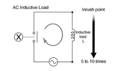
There are several ways to reduce the impact of ILs on an electrical system. One way is to improve the PF of the system by adding PF correction capacitors. These capacitors can help offset the reactive electricity consumed by ILs, thereby increasing the PF of the system. Another approach is to utilize soft starters or variable frequency drives with electric motors, which can reduce inrush current and minimize voltage fluctuations. Finally, using a high-efficiency supply or reducing the number of ILs in a system can also help reduce the impact of ILs on PQ. To balance inductive and capacitive elements, engineers apply power factor correction techniques that restore efficiency and reduce system losses.

By understanding the different types, measuring the PF, and reducing its impact on a system, electrical engineers can design and operate systems that are more efficient, reliable, and cost-effective.

It's worth noting that they are not the only types of electrical loads that can impact PQ. Capacitive loads, such as capacitors and fluorescent lights, can also introduce reactive power into a system. Additionally, purely resistive loads, such as resistors and incandescent light bulbs, do not introduce reactive power but can still affect PQ in other ways, including the generation of heat.

Understanding the different types of electrical loads and their impact on PQ is essential for designing and operating efficient and reliable electrical systems. While they can introduce reactive power and affect PF, there are ways to minimize their impact and improve PQ. By taking a holistic approach to electrical system design and operation, engineers can create systems that meet the needs of their users while minimizing costs and maximizing efficiency. Since inductive loads influence reactive currents, using the reactive power formula helps quantify their effect on power system design and operation.


Related Articles


View more

Resistances in Parallel

Resistances in parallel share voltage, add conductances, and reduce equivalent resistance; apply Ohm's law, current division, and circuit analysis to compute total R, branch currents, and power distribution in multi-branch networks.


What Are Resistances in Parallel?

Parallel resistors share voltage; total resistance decreases by summing conductances (1/R).

✅ Equivalent 1/Rt = sum(1/Ri); lower than smallest branch

✅ Same voltage across branches; currents split by conductance

✅ Use Ohm's law and current division to size components, power


Resistances in parallel is a common term used in industrial, commercial, and institutional power systems. Therefore, a good understanding of working with resistors in parallel and calculating their various parameters is crucial for maintaining safe and efficient operations. For foundational context, see this overview of electrical resistance for key definitions applied throughout.

It means that when resistors are connected in parallel, they share the same voltage across them. Hence, this means that the resistances are in parallel. This is because the total resistance of the resistors in parallel is less than that of any individual resistor, making it a useful configuration for reducing resistance and increasing current in a circuit. A clear grasp of electrical resistance helps explain why parallel branches draw more current.

Adding more resistors in parallel reduces the circuit's total resistance, increasing the current. However, adding too many resistors in parallel can overload the circuit and cause it to fail. Engineers often verify safe loading using the resistance formula to predict current increases.


Understanding Resistances in Parallel

They refer to the configuration in which two or more resistors are connected side by side across the same voltage points in an electrical circuit. In this arrangement, the voltage across each resistor is the same, while the current is divided among the resistors according to their resistance values. This configuration is commonly used in circuit analysis to simplify complex circuits and determine the equivalent parallel resistance.

When simplifying networks, computing the equivalent resistance streamlines analysis and component selection.


Calculating the Equivalent Resistance

To calculate the equivalent resistance of resistances in parallel, the reciprocal of the equivalent resistance (1/Req) is equal to the sum of the reciprocals of the individual resistances (1/R1 + 1/R2 + ... + 1/Rn). This formula is crucial in resistance calculation and helps engineers design efficient power systems that meet the desired voltage drop and current distribution requirements. A comparable reciprocal relationship appears when evaluating capacitance in series under similar analysis methods.

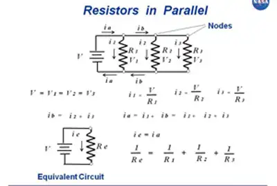
To calculate the total resistance of resistors in parallel, the reciprocal of each resistor is added together, and then the result is inverted to give the total resistance. This can be represented mathematically as:

1/Rt = 1/R1 + 1/R2 + 1/R3 + ...

where Rt is the total resistance and R1, R2, R3, etc. are the individual resistors.


Five resistors R(1) through R(5), connected in parallel, produce a net resistance R.


In a circuit with resistors in parallel, the current is divided among the resistors according to their individual resistance values. This is known as the current division, and it can be calculated using Ohm's law and the circuit's total resistance. The formula for calculating the current through each resistor in parallel is:

I1 = (V/R1) * (R2/(R2 + R3)) I2 = (V/R2) * (R1/(R1 + R3)) I3 = (V/R3) * (R1/(R1 + R2))

where I1, I2, and I3 are the currents through each resistor, V is the voltage across the circuit, and R1, R2, and R3 are the individual resistors.

Simplifying a circuit with resistors in parallel involves finding the equivalent resistance of the circuit. This is the resistance value that would produce the same current as the original parallel circuit, and it can be calculated using the reciprocal formula:

1/Req = 1/R1 + 1/R2 + 1/R3 + ...

where Req is the equivalent resistance.


Impact on Total Resistance

In a parallel configuration, adding more resistors decreases the total resistance. The reason is that the current has multiple paths to flow through, reducing the overall opposition to current flow. This characteristic is particularly useful in designing power supply systems, where lower resistance is desired to minimize energy losses and improve system efficiency. By contrast, capacitance in parallel increases as components are added, offering a helpful design analogy.


Practical Applications

They are employed in various real-life circuits and power systems. For instance, they are commonly found in circuit simulations, power distribution systems, and load balancing applications. In industrial settings, a parallel resistor calculator is often used to measure multiple current paths for fault protection and redundancy. In commercial and institutional power systems, parallel configurations are employed to manage load distribution and ensure system reliability.


Differences between Parallel and Series Connections

In a series circuit, resistors are connected end-to-end, and the current flows consecutively from the source of each resistor. The total resistance in a series circuit equals the sum of individual resistances, and the voltage drop across each single resistor is different. In contrast, they share the same voltage, and the total resistance decreases as more resistors are added. Identifying these connections in a circuit diagram is crucial for proper circuit analysis and design. For direct comparison of methods, review resistance in series to see how sums differ from reciprocals.


Combining Resistances in Parallel and Series

They can be combined with resistances in series within the same circuit. In such cases, equivalent resistances for both parallel and series sections are calculated separately. Then, the total resistance is determined by adding the equivalent resistances of the series and parallel sections. This approach helps engineers analyze complex circuits and design efficient power systems.

They are crucial to industrial, commercial, and institutional power systems. Understanding how to calculate the total resistance, current distribution, and power dissipation of resistors in parallel is essential for maintaining safe and efficient operations. In addition, engineers can optimize their designs for optimal performance by using circuit simulation software and other tools.


Related Articles

View more

Sign Up for Electricity Forum’s Newsletter

Stay informed with our FREE Newsletter — get the latest news, breakthrough technologies, and expert insights, delivered straight to your inbox.

Electricity Today T&D Magazine Subscribe for FREE

Stay informed with the latest T&D policies and technologies.
  • Timely insights from industry experts
  • Practical solutions T&D engineers
  • Free access to every issue

Download the 2025 Electrical Training Catalog

Explore 50+ live, expert-led electrical training courses –

  • Interactive
  • Flexible
  • CEU-cerified