Wireless Electricity


Wireless Electricity

Wireless electricity transmits power without wires using electromagnetic fields, such as magnetic resonance or microwave transmission. It enables charging devices remotely, powering sensors, and improving efficiency in smart grids, EVs, and wireless charging systems.


What is Wireless Electricity?

Wireless electricity refers to the transmission of electrical energy without physical conductors like wires.

✅ Powers devices through electromagnetic fields, like inductive coupling

✅ Enables contactless charging in consumer electronics and EVs

✅ Supports smart grids, IoT, and remote sensors with flexible energy delivery

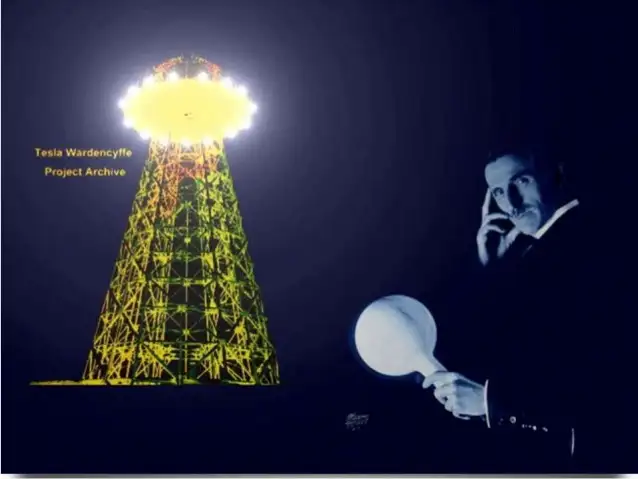
Wireless electricity, also known as wireless power transmission, was first conceptualized by Nikola Tesla, a pioneer in the field of alternating current (AC) electricity. Tesla’s groundbreaking experiments at Colorado Springs in 1899 showcased how power could be transmitted without wires using a magnetic field. He used a Tesla coil to transmit 100 million volts of high power over a distance of 26 miles, wirelessly powering 200 light bulbs and an electric motor. His vision was to develop a wireless system capable of transmitting power over long distances with minimal energy loss.

Tesla’s system relied on a high-frequency alternating current and magnetic resonance to transmit power wirelessly. His experiments with the Tesla coil laid the groundwork for modern wireless technologies, including short-range wi

reless power transmission systems, such as wireless charging pads and Wi-Fi routers. Wireless charging pads today utilize magnetic fields to transmit power to devices, a concept similar to Tesla’s idea of harnessing the Earth’s resonance to transmit power over longer distances. Tesla’s vision extended beyond short-range wireless systems—he dreamed of a global system where energy flows freely through the air without requiring a direct line of sight.

Tesla’s experiments also demonstrated the efficiency of wireless systems. The Tesla coil could transmit power wirelessly to fluorescent light bulbs even when they were several feet away from the coil. This concept of powering devices wirelessly has evolved over time, with companies like Wi-Charge developing systems to transmit power wirelessly to small devices. In Tesla’s time, he envisioned a world where any amount of power could be transmitted wirelessly across the globe. However, financial struggles eventually led to the abandonment of his wireless power transmission projects, including the unfinished Wardenclyffe tower on Long Island. Devices powered wirelessly still rely on efficient energy flow, making concepts such as electrical resistance and impedance crucial to design and performance.

Despite Tesla’s challenges, modern advancements have kept his vision alive. Short-range wireless power transmission systems, like those used in Wi-Fi routers and wireless charging pads, are now commonplace. These technologies utilize magnetic fields to transmit power wirelessly over short distances, offering a practical solution for wirelessly charging devices such as smartphones and laptops. Wi-Charge is exploring the potential of wirelessly charging devices without requiring close contact, enabling more flexible and efficient energy distribution. Tesla’s coil and modern systems like Wi-Charge operate based on resonant principles, closely related to inductance and capacitance.


Modern Innovations in Wireless Electricity

Recent breakthroughs have brought Tesla’s dream closer to reality:

  • In 2024, DARPA successfully transmitted 800 watts of power over 5 miles using a laser beam—enough to make popcorn at the receiver site.

  • KAIST in South Korea demonstrated the ability to charge 40 smartphones at once using magnetic resonance over a distance of 5 meters.

  • Detroit’s Corktown district now hosts a functioning inductive charging roadway, allowing EVs to charge wirelessly while in motion.

These examples show that wireless electricity is no longer a distant vision but a rapidly advancing technology with real-world applications. Concepts such as watts, volts, and amperes remain fundamental even in advanced wireless systems.


Types of Wireless Power Transmission Technologies

Technology Type Description and Use Cases
Inductive Coupling Short-range charging pads for phones, laptops, and wearables
Magnetic Resonance Mid-range charging for larger devices and multiple receivers simultaneously
Microwave Transmission Long-range point-to-point energy transfer; used in research and satellites
Laser Power Beaming High-efficiency focused beams for distant targets; demonstrated by DARPA
Infrared Light (Wi-Charge) Contactless charging for smart locks and IoT devices


Applications of Wireless Electricity

  • Consumer Electronics: Wireless charging pads and smart home devices are now common.

  • Electric Vehicles (EVs): Inductive charging roads and parking pads reduce dependency on cable stations.

  • Medical Implants: Enables powering of implants and biosensors without invasive wiring.

  • Remote Sensors: In agriculture, factories, and infrastructure, wireless power extends sensor life.

  • Smart Grids: Flexible energy distribution for remote locations and emergency response.


Challenges and Future Outlook

Despite its promise, wireless electricity faces challenges:

  • Efficiency drops over distance

  • Alignment issues in inductive systems

  • Line-of-sight limitations in laser and IR systems

  • Safety regulations for high-power beaming

However, the future is promising. Emerging materials, such as metamaterials and metasurfaces, are enhancing transmission efficiency. AI-enhanced beam control, dynamic alignment systems, and frequency-agnostic receivers are under development.

From Tesla's early experiments to DARPA's record-setting laser transmission, wireless electricity is evolving into a transformative force. As the technology matures, its applications will expand, powering a world that may one day be truly wire-free.


Related Articles


Related News

Static Electricity

Static electricity is a fascinating phenomenon that can be both awe-inspiring and dangerous. Understanding its basic concepts, including the movement of charged particles and the causes of positive and negative charge imbalance, is crucial in preventing potential hazards. By taking preventive measures such as grounding equipment and surfaces, using anti-static materials, and increasing humidity, we can avoid the buildup of static charges and protect ourselves and our environment from its hazards. It is also important to understand the potential dangers and take appropriate precautions, particularly when working with flammable or explosive materials. With this knowledge, we can safely harness the power and explore its many fascinating properties.


What is static electricity?

It results from the movement of charged particles, called electrons and particles called protons, which make up the atoms of matter. Atoms are made up of protons, neutrons, and electrons. Protons have a positive charge, electrons have a negative charge, and neutrons have no charge. In most atoms, the positive charge of the protons is balanced by the negative charge of the electrons, resulting in a neutral object.

However, when two objects come in contact, the extra electrons from one object may transfer to the other, creating a charge imbalance. This results in one object having a positive charge and the other having a negative electric charge. These charges repel, and when the objects are separated, they retain the charges, creating a static charge.


What causes static electricity?

As previously mentioned, it is caused by the movement of charged particles. When there is a charge imbalance between two objects, it can create a static charge. This can occur through friction, conduction, or induction.

Friction occurs when two objects rub against each other, causing electrons to transfer from one object to the other. For example, this is why you may experience it when you rub a balloon against your hair, causing your hair stand to stand up.

Conduction occurs when two objects come in contact and transfer electrons between them. For example, when you touch a doorknob, you may receive a static shock if the doorknob is charged.

Induction occurs when a charged object is brought near a neutral object, causing a charge to be induced in the neutral object.


How does static electricity work?

It creates a charge imbalance between two objects, resulting in one object having a positive charge and the other having a negative charge. These charges repel each other, and when the objects are separated, they retain the charges, creating a static charge.

When a charged object comes in contact with a neutral object, the charge may transfer, resulting in a static shock. This occurs when the charge imbalance is released as a spark. Static shocks are usually harmless but can sometimes be dangerous, particularly in hazardous environments.


Can static electricity hurt you?

While it is usually harmless, it can sometimes be dangerous. A static shock occurs when a charged object comes in contact with a person or object that is not charged. The shock results from the charge imbalance being released as a spark. The shock can be uncomfortable, and in rare cases, it can cause serious injury, mainly if it occurs in a hazardous environment, such as around flammable materials.


What are the dangers of static electricity?

It can be dangerous in certain situations, such as when working with flammable or explosive materials. A spark from it can ignite flammable gases or vapours, leading to fires or explosions. In industrial settings, it is important to take precautions to prevent the buildup of static charges and to discharge any charges that may occur.


How do you discharge static electricity?

There are several ways to discharge it, including:

  • Grounding: Connecting the charged object to a ground source such as the earth, which dissipates the excess charge.
  • Anti-static materials: Wearing clothes made of anti-static materials or using anti-static sprays can prevent the buildup of static charges.
  • Humidification: Increasing the humidity in a room can help reduce a buildup by adding moisture to the air.
  • Use of ionizers: Ionizers can neutralize it by releasing negative ions into the air.
  • Proper grounding of equipment: Ensuring that all equipment and surfaces are properly grounded can prevent the buildup of static charges.


How can you prevent static electricity?

Preventing buildup involves taking several steps, such as:

  • Using anti-static materials: Clothing made of anti-static materials or anti-static sprays can prevent the buildup of static charges.
  • Grounding: Ensuring that all equipment and surfaces are properly grounded can prevent the buildup of static charges.
  • Humidification: Increasing the humidity in a room can help reduce a buildup by adding moisture to the air.
  • Proper handling of flammable materials: When working with flammable or explosive materials, it is important to take proper precautions to prevent a buildup and discharge of any charges.
  • Using equipment designed for use in hazardous environments: Equipment designed for use in hazardous environments is designed to prevent a buildup and sparks from occurring.

In addition to these preventive measures, it is important to understand the basics of static electricity and the factors that contribute to its buildup. This knowledge can help individuals take steps to avoid buildup and prevent any potential hazards.


Van de Graaff Generator: An Experiment with Static Electricity

One fascinating example of this is the Van de Graaff generator. This device was invented in 1929 by Robert J. Van de Graaff and is used to generate high voltages of static electricity. The generator transfers electrons from a moving belt to a metal sphere, creating a charge imbalance between the two objects.

This charge imbalance creates a strong electric field, which can be used to demonstrate various phenomena. For example, the electric field can cause hairs on a person's head or arm to stand up due to the repulsion between the positively charged hair and the positively charged metal sphere.


View more

Electricity Cost Principles Explained

Electricity cost reflects kWh rates, tariffs, demand charges, power factor penalties, and TOU peak/off-peak pricing, driven by load profiles, utility billing, transmission and distribution fees, and efficiency measures in industrial, commercial, and residential systems.


What Is Electricity Cost?

Electricity cost is the total price per kWh including energy, demand, and network charges under applicable tariffs.

✅ Includes energy (kWh), demand (kW), and fixed charges

✅ Varies by TOU tariffs, peak/off-peak, and seasons

✅ Affected by power factor, load profile, and efficiency


Electricity Cost principles involve looking at how much electricity consumption and we have to understand how it's measured.

At its core, understanding power use starts with grasping what electricity is and how it behaves in circuits.

It is determined at any moment and is measured in watts consumed. For example: if you want to determine the bill energy or bill electricity rate: For a refresher, see what a watt represents to relate device ratings to instantaneous power.

  • A 100-watt light bulb uses 100 watts.
  • A typical desktop computer uses 65 watts.
  • A central air conditioner uses about 3500 watts.

These device ratings illustrate electric load in practical terms as each appliance contributes to total demand.

If you want to know how to rate electricity pricing, you want to know how much energy you're using. When you use 1000 watts for an hour, that's a kilowatt-hour. For example:

  • Ten 100-watt light bulbs on for an hour, is 1 kWh
  • Ten 100-watt light bulbs on for 1/2 an hour, is 0.5 kWh
  • Ten 50-watt light bulbs on for an hour, is 0.5 kWh
  • One 60-watt light bulb on for an hour, is 0.06 kWh (60/1000)
  • Running a 3500-watt air conditioner for an hour is 3.5 kWh.

The average U.S. household used 10,654 kWh a year in 2001, or 888 kWh/mo. (Dept. of Energy) The U.S. as a whole used 3,883 billion kWh in 2003, or 13,868 kwH per person based on a population of 300 million. (Dept. of Energy)


Watt-hours

For smaller items we use the term watt-hours instead of kilowatt-hours. For example, we say a 60-watt light bulb uses 60 watt-hours of electricity billed, not 0.060 kWh. If you're unsure, this overview of what a watt-hour means clarifies the relationship between power and time.

Note that the "-hours" part is important. Without it we'd have no idea what period of time we were talking about.

If you ever see a reference without the amount of time specified, it's almost certainly per hour.

If your device lists amps instead of watts, then just multiply the amps times the voltage to get the watts. For example:

2.5 amps x 120 volts = 300 watts

Trivia: On a peak day in 2009, California used 50,743 megawatt-hours of electricity, or 50,743,000,000 watt-hours.

How much does electricity cost?


Electricity Cost

It depends on where you live (like Ontario), how much you use, and possibly when you use it. There are also fixed charges that you pay every month no matter how much electricity you use. For example, I pay $6/mo. for the privilege of being a customer of the electric company, no matter how much energy I use. Local infrastructure and electricity supply conditions can also influence pricing tiers.

Check your utility bill for the rates in your area. If it's not on your bill then look it up on the utility's website. National summaries of electricity prices help you compare trends across regions.

The electric company measures how much electricity you use in kilowatt-hours. The abbreviation for killowatt-hour is kWh. Note that on your bill there can be multiple charges per kWh (e.g., one for the "base rate", another for "fuel") and you have to add them all up to get the total cost per kWh. This measurement is recorded by a watt-hour meter that cumulatively tracks energy over time.

Most utility companies charge a higher rate when you use more than a certain amount of energy, and they also charge more during summer months when electric use is higher. As an example, here are the residential rates prices electricity for Austin, Texas (as of 11-03):

First 500 kilowatts5.8¢ per kilowatt hour (kWh)

Additional kilowatts (May-Oct.)10¢ per kilowatt hour

Additonal kilowatts (Nov.-Apr.)8.3¢ per kilowatt hour

These figures include a fuel charge of 2.265¢ per kWh.

The average cost of residential electricity was 9.86¢/kWh in the U.S. in March 2006. The average household used 888 kWh/mo. in 2001 and would pay $87.56 for it based on the March 2006 average rate. (Dept. of Energy)

The cost of electricity varies by region. In 2003 the price ranged from 5.81¢ in Tennessee to 12¢ in California, 14.314¢ in New York, and 16.734¢ in Hawaii. In Summer 2001, electricity was a whopping 20¢/kWh in parts of California.


Related Articles

View more

Voltage Explained

Voltage is the electric potential difference that drives current through a circuit. It relates to energy conversion, electrical work, power, density, and forms of electricity, explained through principles of conservation and thermodynamics.


What is Voltage?

Voltage is the measure of the electrical potential difference between two points, representing the force that pushes electrons and enables the transfer of energy.

✅ Determines current flow in a circuit

✅ Relates to work, power, and energy conversion

✅ Fundamental to electrical systems and safety


Definition

Voltage (V, EMF, or E) is electrical pressure, a potential force or difference in electrical charge between two points in an electric circuit. Voltage pushes current through a wire, much like water pressure pushes water through a pipe. The level of voltage is proportional to the difference in potential electrical energy between two points. Voltage is measured in volts (V).

  • One volt equals one joule of work per coulomb of charge: V = W/Q

  • Voltage across a resistor follows Ohm’s law: V = I·R

  • Electrical power relates to voltage as P = V·I

A voltage of one volt is required to force one ampere of current through one ohm of resistance. The letter E, which stands for electromotive force (EMF), or V, which stands for volt, is commonly used to represent voltage in formulas. In three-phase systems, voltage plays a critical role in balancing loads and ensuring efficient 3 phase electricity distribution.


Voltage and the Electric Field

Voltage, or potential difference, exists between any two charges that are not equal. Even an uncharged body has a potential difference relative to a charged one. More formally, voltage is linked to the electric field by the relation:

dV/dx = –E

This shows that voltage is the integral of the electric field across a distance. Voltage itself does not flow like current; instead, it exists between two points and provides the force that moves charge when a conductive path is present. A change in voltage across a circuit directly affects the flow of active power and reactive power in modern electrical systems.


DC vs AC Voltage

  • DC Voltage: A steady, unchanging potential difference (like that from a battery).

  • AC Voltage: A time-varying voltage, often sinusoidal in form, alternating between positive and negative values.

AC voltages are described by different measures:

  • Peak voltage: the maximum value reached.

  • RMS (root mean square) voltage: the effective value that produces the same heating effect as DC. For a sinusoidal wave, Vrms = Vpeak/√2.

Visualizing AC voltage as a waveform helps illustrate these differences. In power distribution, nominal voltage ratings are carefully selected to optimize 3 phase power delivery while ensuring electricity safety.


Voltage Sources

  • Ideal sources: Supply a constant voltage regardless of current drawn.

  • Real sources: Contain internal resistance, so voltage drops as load current increases.

This explains why batteries or generators cannot maintain voltage perfectly under heavy load. Voltage sag is a common power quality issue that impacts electrical resistance and the performance of sensitive electrical energy devices.


Measuring Voltage

A voltmeter measures the potential difference between two points. It must be connected across the component, not in series, because voltage is defined between points, not through them. Very small voltages are measured in millivolts and microvolts, while very large ones are expressed in kilovolts and megavolts. To measure voltage accurately, electricians rely on instruments like the voltmeter or multimeter, which are essential for diagnosing electrical circuits.


Voltage, Resistance, and Ohm’s Law

Electrical resistance (R) is the opposition to the flow of electrons (current). It can be compared to friction that slows motion. Resistance is measured in ohms (Ω).

Resistance arises partly because atoms resist losing electrons to the positive nucleus, and partly due to collisions between moving electrons and atoms. This resistance produces heat, which is why wires warm up when current flows. Heating elements and lamp filaments operate on this principle, as their high resistance converts electrical energy into light and heat.

Every electrical component has some resistance, and resistance changes electrical energy into other forms such as heat, light, or motion.

An ohmmeter is used to measure resistance when no current is flowing. Most multimeters include an ohmmeter function powered by an internal battery. For this reason, ohmmeters should never be connected to live circuits.

Ohm’s Law ties resistance directly to voltage: V = I·R. The higher the resistance, the greater the voltage required to drive a given current. The relationship between voltage, current, and resistance is the foundation of Ohm’s Law, which underpins all basic electricity concepts.


Safety Considerations

Voltage is directly tied to safety in electrical systems. High voltages can break down insulation, ionize air, and cause arcing or shock hazards.

  • Breakdown voltage: The point at which insulation fails and current flows uncontrollably.

  • Dielectric strength: A material’s maximum withstand voltage before breakdown.

  • Ratings: All equipment is equipped with voltage ratings to ensure safe operation.

Understanding these factors is critical for designing and maintaining safe electrical systems.


Worked Examples

  1. Simple resistor: A 2 A current flows through a 5 Ω resistor. Voltage = I·R = 2 × 5 = 10 V.

  2. Power relation: A device consumes 100 W at 5 A. Voltage = P/I = 100 ÷ 5 = 20 V.

  3. AC RMS: If Vpeak = 170 V, then Vrms = 170/√2 ≈ 120 V, the common household supply.


History and Applications

The unit “volt” is named after Alessandro Volta, the Italian scientist who pioneered the first chemical battery, the voltaic pile. His work established the foundation of the modern history of electricity.

Today, voltage underpins every electrical system, from the smallest microchip to the largest power grid. It enables energy transfer, communication, motion, and the transmission of light.


Frequently Asked Questions


Can voltage exist without current?

Yes. Voltage can be present even if no current flows. A battery not connected to a circuit still has a measurable voltage.


What’s the RMS voltage?

It is the effective value of an alternating voltage that produces the same heating effect as a direct voltage.


What is safe voltage?

Safe limits depend on the context, but typically 50 V or less is considered a threshold below which the risk of shock is reduced, although not eliminated.


Related Articles


View more

Voltage Drop Explained

Voltage drop occurs when electrical voltage decreases as current flows through a conductor. It can cause poor equipment performance, energy loss, and overheating. Discover how selecting the proper wire size and material can help minimize voltage drop in electrical systems.

Power Quality Analysis Training

Power Factor Training

Request a Free Power Quality Training Quotation


What is Voltage Drop?

Voltage drop (VD) is a common issue in electrical systems where the voltage (V) at the end of a circuit is lower than at the beginning due to resistance in the wiring.

✅ A decrease in V along a wire or circuit due to resistance or impedance

✅ Leads to reduced equipment performance and higher energy consumption

✅ Prevented by proper wire sizing, shorter runs, and low-resistance materials


Voltage Drop Definition

Voltage drop can lead to inefficient equipment operation or even failure. Solving electrical potential drop involves ensuring proper wire sizing, minimizing long-distance wiring runs, and using materials with lower resistance. Calculating the voltage drop for specific circuits and adjusting the installation accordingly helps maintain optimal performance and prevent power loss.

Any length or size of wires will have some resistance, and running a current through this dc resistance will cause the voltage to drop. As the length of the cable increases, so does its resistance and reactance increase in proportion. Hence, circuit V drop is particularly a problem with long cable runs, for example, in larger buildings or on larger properties such as farms. This technique is often used when properly sizing conductors in any single-phase, line-to-line electrical circuit. This can be measured with a voltage drop calculator.

Electrical cables have a carrying capacity of current that always presents inherent resistance, or impedance, to the flow of current. Voltage drop is measured as the amount of loss which occurs through all or part of a circuit due to what is called cable "impedance" in volts.

Too much resistance in wires, otherwise known as " excessive voltage drop ", in a cable's cross-sectional area can cause lights to flicker or burn dimly, heaters to heat poorly, and motors to run hotter than normal and burn out. This condition causes the load to work harder with less energy, pushing the current.


Voltage Drop per 100 Feet of Copper Wire (Single Phase, 60 Hz, 75°C, 120V Circuit)

(Values are approximate, in volts, for a 2% limit)

Wire Size (AWG) Max Current (Amps) Max Distance (Feet) Voltage Drop (at max distance)
14 15 50 2.4 V
12 20 60 2.4 V
10 30 80 2.4 V
8 40 100 2.4 V
6 55 130 2.4 V
4 70 160 2.4 V
2 95 200 2.4 V
1/0 125 250 2.4 V


Key Takeaways

  • Larger wires (lower AWG numbers) carry more current with less VD.

  • Longer distances require thicker wires to stay within VD limits.

  • A 2% VD is often used as a conservative design target in electrical systems.


How is this solved?

To decrease the voltage drop in a circuit, you need to increase the size (cross-section) of your conductors – this is done to lower the overall resistance of the cable length. Certainly, larger copper or aluminum cable sizes increase the cost, so it’s essential to calculate the voltage drop and determine the optimum wire size that will reduce voltage drop to safe levels while remaining cost-effective.


How do you calculate voltage drop?

Voltage drop refers to the loss of electricity that occurs when current flows through a resistance. The greater the resistance, the greater the voltage drop. To check the voltage drop, use a voltmeter connected between the points where the voltage drop is to be measured. In DC circuits and AC resistive circuits, the total of all the voltage drops across series-connected loads should add up to the V applied to the circuit (Figure 1).


Fig. 1. Measuring voltage drops across loads

Read our companion article Voltage Drop Calculator. For more information, see our article: Voltage Drop Formula.

Each load device must receive its rated power to operate properly. If not enough is available, the device will not operate as it should. You should always be certain that the V you are going to measure does not exceed the range of the voltmeter. This may be difficult if the V is unknown. If such is the case, you should always start with the highest range. Attempting to measure a V higher than the voltmeter can handle may cause damage to the voltmeter. At times you may be required to measure a V from a specific point in the circuit to ground or a common reference point (Figure 8-15). To do this, first connect the black common test probe of the voltmeter to the circuit ground or common. Then connect the red test probe to whatever point in the circuit you want to measure.

To accurately calculate the drop for a given cable size, length, and current, you need to accurately know the resistance of the type of cable you’re using. However, AS3000 outlines a simplified method that can be used.

The table below is taken from AS3000 electrical code, which specifies ‘Amps per %Vd‘ (amps per percentage VD) for each cable size.  To calculate the dop for a circuit as a percentage, multiply the current (amps) by the cable length (metres); then divide this Ohm number by the value in the table.

For example, a 30m run of 6 mm² cable carrying 3-phase 32A will result in a 1.5% drop: 32A × 30m = 960A / 615 = 1.5%.

Learn more about real-world voltage drop issues on our Voltage Dropping in Power Quality page.


Related Pages


View more

Watthour Meter Explained

A watthour meter measures electrical energy consumption in kilowatt-hours (kWh) for residential, commercial, and industrial applications, ensuring accurate billing, energy management, and compliance with utility standards.


What is a Watthour Meter?

✅ Measures total electrical energy in kilowatt-hours (kWh) over time

✅ Supports accurate billing, energy monitoring, and demand analysis

✅ Used in residential, commercial, and industrial revenue metering


Advancements in Watthour Meter Technology and Energy Measurement

Watthour meter technology plays a crucial role in modern electrical engineering and maintenance by providing accurate measurement and monitoring of energy consumption. These devices are indispensable for managing energy efficiency, optimizing power distribution, and ensuring compliance with regulatory standards. For electrical professionals, understanding how they operate and are maintained is essential to minimize energy losses and enhance the reliability of electrical systems. With the growing demand for precise energy data in both residential and industrial applications, staying informed about advancements in watthour meter technology is more important than ever. Understanding how a watthour is calculated helps clarify how a watthour meter tracks total energy usage for accurate billing. 


How Induction Type Single Phase Watt Hour Meters Work

Induction type meters, commonly used as single phase watt hour meters, provide accurate measurement of electrical energy consumption in residential and small commercial installations.

Your electric utility is not too interested in how much power you're consuming for one ap­pliance or even how much power a single household is drawing at any given time. By far the greater concern is the total energy that is used over a day, a week, a month or a year. Electrical energy is measured in watt-hours or, more commonly for utility pur­poses, in kilowatt-hours (kWh). The device that measures this consumption is the watt-hour meter or kilowatt-hour meter. For a deeper understanding of the units used in metering, see our guide on electrical energy and how it is measured in kilowatt-hours.

The most common method for measuring electrical energy is by using a small elec­tric motor device, whose speed depends on the current, and thereby on the power at a constant voltage. The number of turns of the motor shaft, in a given length of time, is di­rectly proportional to the number of watt hours consumed. The motor is placed at the point where the utility wires enter the house, apartment or building. This is usually at a point where the voltage is 234 V. This is split into some circuits with 234 V, for heavy-duty appliances such as the oven, washer and dryer, and the general household circuits for lamps, clock radios and television sets. The principles behind watthour meters are closely tied to basic electricity and the relationship between active power and time.


Understanding the Spinning Disk in Electromechanical Watthour Meters

You've surely seen the little disk in the utility meter going around and around, sometimes fast, other times slowly. Its speed depends on the power you're using. The total number of turns of this little disk, every month, determines the size of the bill you will get, as a function also, of course, of the cost per kilowatt hour for electricity.

Kilo-watt-hour meters count the number of disk turns by means of geared, rotary drums or pointers. The drum-type meter gives a direct digital readout. The pointer type has several scales calibrated from 0 to 9 in circles, some going clockwise and others go­ing counterclockwise. Mechanical and electronic meters both rely on the concepts of electrical resistance and current to provide precise readings.


How to Read a Pointer-Type Watthour Meter Accurately

Reading a pointer-type utility meter is a little tricky because you must think in whatever direction (clockwise or counterclockwise) the scale goes. An example of a pointer-type utility meter is shown in Fig. 3-11. Read from left to right. For each little meter, take down the number that the pointer has most recently passed. Write down the rest as you go. The meter in the figure reads 3875 kWh. If you want to be really pre­cise, you can say it reads 3875-1/2 kWh. To place watt hour metering in historical context, explore our history of electricity page and learn how early meters evolved into today’s advanced devices.


Fig. 3-11 An example of a utility kilo-watthour meter. The reading is a little more than 3875 kWh.


Related Articles


View more

Voltage Drop Formula

The voltage drop formula is V = I × R, where V represents the voltage drop, I represents the current in amperes, and R represents the resistance in ohms. It calculates the amount of voltage lost through a conductor and is essential for designing safe and efficient electrical systems.


What is Voltage Drop Formula?

A voltage drop formula can help you manually calculate the voltage drop in cables under full load in branch circuits. It does not matter if you are working with copper or aluminum conductors. To accurately calculate the voltage drop for a given cable size, length, and current, you need to know the resistance of the type of cable you’re using. 

✅ V = I × R for DC circuits

✅ Accounts for impedance in AC circuits

✅ Helps ensure safe, efficient electrical design

Use our voltage drop calculator to quickly determine wire size, conductor efficiency, and line loss for safer, more reliable electrical installations.


Power Quality Analysis Training

Power Factor Training

Request a Free Power Quality Training Quotation

To determine voltage drop in an electrical system, engineers and electricians use a standard formula that accounts for conductor resistance, current, and circuit length. The National Electrical Code (NEC) provides guidelines for the maximum voltage drop allowed in various installations to ensure efficiency and safety. For both single-phase and three-phase circuits, excessive voltage drop can lead to poor equipment performance and energy loss. To simplify calculations, a voltage drop calculator can quickly assess whether a circuit meets NEC recommendations and optimize conductor sizing accordingly. You can learn more about how electrical resistance affects circuits in our detailed voltage drop guide, which explains causes, calculations, and solutions for safe, efficient power distribution.


DC / single phase calculation

The voltage drop V in volts (V) is equal to the wire current I in amps (A) times 2 times one way wire size length L in feet (ft) times the wire resistance per 1000 feet R in ohms (Ω/kft) divided by 1000:


Vdrop (V) = Iwire (A) × Rwire(Ω)

Iwire (A) × (2 × L(ft) × Rwire(Ω/kft) / 1000(ft/kft))


The voltage drop V in volts (V) is equal to the wire current I in amps (A) times 2 times one way wire length L in meters (m) times the wire resistance per 1000 meters R in ohms (Ω/km) divided by 1000:


Vdrop (V) = Iwire (A) × Rwire(Ω)

Iwire (A) × (2 × L(m) × Rwire (Ω/km) / 1000(m/km))


3 phase calculation

The line-to-line voltage drop V in volts (V) is equal to the square root of 3 times the wire current I in amps (A) times one-way wire length L in feet (ft) times the wire resistance per 1000 feet R in ohms (Ω/kft) divided by 1000:


Vdrop (V) = √3 × Iwire (A) × Rwire (Ω)

= 1.732 × Iwire (A) × (L(ft) × Rwire (Ω/kft) / 1000(ft/kft))


The line-to-line voltage drop V in volts (V) is equal to the square root of 3 times the wire current I in amps (A) times one-way wire length L in meters (m) times the wire resistance per 1000 meters R in ohms (Ω/km) divided by 1000:


Vdrop (V) = √3 × Iwire (A) × Rwire (Ω)

= 1.732 × Iwire (A) × (L(m) × Rwire (Ω/km) / 1000(m/km))


Wire diameter calculations

The n gauge wire diameter, dn in inches (in), is equal to 0.005in times 92 raised to the power of 36 minus gauge number n, divided by 39:


dn (in) = 0.005 in × 92(36-n)/39


The n gauge wire diameter dn in millimetres (mm) is equal to 0.127mm times 92 raised to the power of 36 minus gauge number n, divided by 39:


dn (mm) = 0.127 mm × 92(36-n)/39


Wire cross-sectional area calculations

The n gauge wire's cross-sectional area An in kilo-circular mils (kcmil) is equal to 1000 times the square wire diameter d in inches (in):


An (kcmil) = 1000×dn2 = 0.025 in2 × 92(36-n)/19.5


The n gauge wire's cross-sectional area An in square inches (in2), is equal to pi divided by 4 times the square wire diameter d in inches (in):


An (in2) = (π/4)×dn2 = 0.000019635 in2 × 92(36-n)/19.5


The n gauge wire's cross-sectional area, An, in square millimetres (mm2), is equal to pi divided by 4 times the square wire diameter d in millimetres (mm):


An (mm2) = (π/4)×dn2 = 0.012668 mm2 × 92(36-n)/19.5


Wire resistance calculations

The n gauge wire resistance R in ohms per kilofeet (Ω/kft) is equal to 0.3048×1000000000 times the wire's resistivity ρ in ohm-meters (Ω·m) divided by 25.42 times the cross-sectional area An in square inches (in2):


R(Ω/kft) = 0.3048 × 10⁹ × ρ(Ω·m) / (25.42 × An (in2))


The n gauge wire resistance R in ohms per kilometre (Ω/km) is equal to 1000000000 times the wire's resistivity ρ in ohm-meters (Ω·m) divided by the cross-sectional area An in square millimetres (mm2):


R(Ω/km) = 109 × ρ(Ω·m) / An (mm2)


Related Pages


View more

Sign Up for Electricity Forum’s Newsletter

Stay informed with our FREE Newsletter — get the latest news, breakthrough technologies, and expert insights, delivered straight to your inbox.

Electricity Today T&D Magazine Subscribe for FREE

Stay informed with the latest T&D policies and technologies.
  • Timely insights from industry experts
  • Practical solutions T&D engineers
  • Free access to every issue

Live Online & In-person Group Training

Advantages To Instructor-Led Training – Instructor-Led Course, Customized Training, Multiple Locations, Economical, CEU Credits, Course Discounts.

Request For Quotation

Whether you would prefer Live Online or In-Person instruction, our electrical training courses can be tailored to meet your company's specific requirements and delivered to your employees in one location or at various locations.