Kirchhoff's Law

By R.W. Hurst, Editor

Kirchhoff's law

Kirchhoff's Law, comprising the Current Law (KCL) and Voltage Law (KVL), governs electrical circuits by ensuring charge conservation and energy balance, essential for analyzing current flow, voltage drops, and network behaviour.


What is Kirchhoff's Law?

Kirchhoff's law is an essential principle in the analysis of electrical circuits, enabling a comprehensive understanding of the behaviour of complex circuits.

✅ Defines relationships between currents and voltages in electrical circuits

✅ Ensures conservation of charge (KCL) and energy (KVL) in networks

✅ Essential for analyzing and solving complex circuit problems

It consists of two fundamental rules, Kirchhoff's Current Law (KCL) and Kirchhoff's Voltage Law (KVL), which are intrinsically linked to other electricity laws, such as Ohm's law.  Kirchhoff’s Law works closely with Ohm’s Law Formula to calculate voltage drops, currents, and resistance in electrical networks.

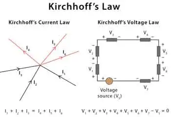
Kirchhoff's Current Law (KCL) - Also known as the first Kirchhoff's law or Kirchhoff's junction rule, KCL states that the sum of the currents entering a junction in a circuit is equal to the sum of the currents leaving the junction. Mathematically, it can be expressed as:

ΣI_in = ΣI_out

KCL is based on the principle of the conservation of charge, asserting that charge can neither be created nor destroyed. In practical terms, KCL means that, at any given point in a circuit, the total current entering must equal the total current leaving, ensuring a continuous flow of electric charge. Understanding Basic Electricity provides the foundation for applying Kirchhoff’s Current Law and Voltage Law to real-world circuit analysis.

Kirchhoff's Voltage Law (KVL) - Also known as the second Kirchhoff's law or Kirchhoff's loop rule, KVL states that the sum of the voltage gains and losses (potential differences) around any closed loop in a circuit is zero. Mathematically, it can be expressed as:
ΣV_rise = ΣV_drop

KVL is based on the principle of the conservation of energy, indicating that energy cannot be created or destroyed but can only be converted from one form to another. In electrical circuits, KVL implies that the total voltage supplied in a loop equals the total voltage drop across all components, ensuring that energy is conserved. Accurate circuit calculations require a clear grasp of Electrical Resistance and how it impacts voltage distribution across components.


Relation to Other Electricity Laws

The most significant connection between Kirchhoff's and other electricity laws is Ohm's law, which defines the relationship between voltage, current, and resistance in an electrical circuit. Ohm's law can be expressed as:

V = IR

When analyzing a circuit using Kirchhoff's laws, Ohm's law is often employed to calculate unknown quantities such as voltage drops, currents, or resistance values. By combining Kirchhoff's laws with Ohm's law, a complete understanding of the behaviour of electrical circuits can be achieved, facilitating efficient design, troubleshooting, and optimization. Applying Kirchhoff’s principles is easier when you understand key Electrical Terms used in engineering and troubleshooting.


History

Gustav Robert Kirchhoff, a German physicist, made significant contributions to understanding electrical circuits by establishing two fundamental laws: Kirchhoff's Voltage Law (KVL) and Kirchhoff's Current Law (KCL). These laws are essential tools for circuit analysis, enabling engineers to design and troubleshoot electrical networks efficiently. In addition to resistance, Capacitance plays a vital role in determining circuit behavior, especially in AC systems.

KVL, also known as the loop rule, states that the algebraic sum of all the voltages around a closed loop equals zero. This principle is derived from the conservation of energy, which ensures that no energy is lost within a closed system. In essence, KVL states that the energy supplied to a circuit is equal to the energy consumed by the components in that circuit. Therefore, when solving problems using KVL, it is essential to consider voltage drops across resistive elements like resistors and voltage rises due to sources like batteries or generators.

On the other hand, KCL, or the junction rule, states that the algebraic sum of currents entering a junction (node) in a circuit is equal to the sum of currents leaving the same junction. This law is a consequence of the conservation of charge, which posits that charge cannot be created or destroyed within an electrical circuit. KCL ensures that the total charge entering and leaving a node remains constant, with the currents (I1, I2, I3, I4, I5) balancing each other. Knowledge of Voltage Drop is essential when using KVL to assess energy losses in electrical circuits.

The significance of these laws in electrical networks lies in their versatility, as they can be applied to a wide range of circuits, from simple series and parallel circuits to more complex electrical networks. Kirchhoff's laws can be employed in conjunction with Ohm's Law, which states that the current through a conductor is proportional to the voltage across it and inversely proportional to its resistance. Using Kirchhoff's and Ohm's Law, engineers can analyze various aspects of a circuit, including voltage drops, current flow, and power distribution.

When analyzing series and parallel circuits, his laws offer valuable insight into the behaviour of electrical components. In series circuits, the current remains constant throughout the entire loop, while the voltage drops across each resistor are proportional to their respective resistances. The voltage across each branch is constant in parallel circuits, but the current is divided among the parallel resistors according to their resistances. By applying KVL and KCL to these configurations, engineers can determine the optimal arrangement of components for a given application.

To illustrate the application of his laws, consider a simple example. Imagine a circuit with a battery, two resistors in series, and a capacitor in parallel with the second resistor. By applying KVL and KCL, we can determine the voltage drop across each resistor, the current flow through each branch, and the voltage across the capacitor, enabling us to analyze the circuit's behaviour under various conditions.

Despite their usefulness, his laws have some limitations and assumptions. For instance, they assume that the components in a circuit are ideal, meaning they have no internal resistance or capacitance. Additionally, they don't account for the effects of electromagnetic fields or the finite speed of signal propagation in AC circuits. However, these limitations are often negligible in many practical applications, as they only marginally impact circuit performance. For a deeper historical context, explore the History of Electricity and the contributions of Gustav Kirchhoff to modern circuit theory.


Related Articles


Related News

Voltage Explained

Voltage is the electric potential difference that drives current through a circuit. It relates to energy conversion, electrical work, power, density, and forms of electricity, explained through principles of conservation and thermodynamics.


What is Voltage?

Voltage is the measure of the electrical potential difference between two points, representing the force that pushes electrons and enables the transfer of energy.

✅ Determines current flow in a circuit

✅ Relates to work, power, and energy conversion

✅ Fundamental to electrical systems and safety


Definition

Voltage (V, EMF, or E) is electrical pressure, a potential force or difference in electrical charge between two points in an electric circuit. Voltage pushes current through a wire, much like water pressure pushes water through a pipe. The level of voltage is proportional to the difference in potential electrical energy between two points. Voltage is measured in volts (V).

  • One volt equals one joule of work per coulomb of charge: V = W/Q

  • Voltage across a resistor follows Ohm’s law: V = I·R

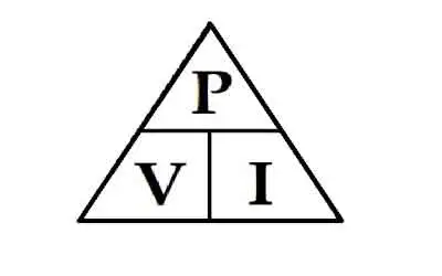
  • Electrical power relates to voltage as P = V·I

A voltage of one volt is required to force one ampere of current through one ohm of resistance. The letter E, which stands for electromotive force (EMF), or V, which stands for volt, is commonly used to represent voltage in formulas. In three-phase systems, voltage plays a critical role in balancing loads and ensuring efficient 3 phase electricity distribution.


Voltage and the Electric Field

Voltage, or potential difference, exists between any two charges that are not equal. Even an uncharged body has a potential difference relative to a charged one. More formally, voltage is linked to the electric field by the relation:

dV/dx = –E

This shows that voltage is the integral of the electric field across a distance. Voltage itself does not flow like current; instead, it exists between two points and provides the force that moves charge when a conductive path is present. A change in voltage across a circuit directly affects the flow of active power and reactive power in modern electrical systems.


DC vs AC Voltage

  • DC Voltage: A steady, unchanging potential difference (like that from a battery).

  • AC Voltage: A time-varying voltage, often sinusoidal in form, alternating between positive and negative values.

AC voltages are described by different measures:

  • Peak voltage: the maximum value reached.

  • RMS (root mean square) voltage: the effective value that produces the same heating effect as DC. For a sinusoidal wave, Vrms = Vpeak/√2.

Visualizing AC voltage as a waveform helps illustrate these differences. In power distribution, nominal voltage ratings are carefully selected to optimize 3 phase power delivery while ensuring electricity safety.


Voltage Sources

  • Ideal sources: Supply a constant voltage regardless of current drawn.

  • Real sources: Contain internal resistance, so voltage drops as load current increases.

This explains why batteries or generators cannot maintain voltage perfectly under heavy load. Voltage sag is a common power quality issue that impacts electrical resistance and the performance of sensitive electrical energy devices.


Measuring Voltage

A voltmeter measures the potential difference between two points. It must be connected across the component, not in series, because voltage is defined between points, not through them. Very small voltages are measured in millivolts and microvolts, while very large ones are expressed in kilovolts and megavolts. To measure voltage accurately, electricians rely on instruments like the voltmeter or multimeter, which are essential for diagnosing electrical circuits.


Voltage, Resistance, and Ohm’s Law

Electrical resistance (R) is the opposition to the flow of electrons (current). It can be compared to friction that slows motion. Resistance is measured in ohms (Ω).

Resistance arises partly because atoms resist losing electrons to the positive nucleus, and partly due to collisions between moving electrons and atoms. This resistance produces heat, which is why wires warm up when current flows. Heating elements and lamp filaments operate on this principle, as their high resistance converts electrical energy into light and heat.

Every electrical component has some resistance, and resistance changes electrical energy into other forms such as heat, light, or motion.

An ohmmeter is used to measure resistance when no current is flowing. Most multimeters include an ohmmeter function powered by an internal battery. For this reason, ohmmeters should never be connected to live circuits.

Ohm’s Law ties resistance directly to voltage: V = I·R. The higher the resistance, the greater the voltage required to drive a given current. The relationship between voltage, current, and resistance is the foundation of Ohm’s Law, which underpins all basic electricity concepts.


Safety Considerations

Voltage is directly tied to safety in electrical systems. High voltages can break down insulation, ionize air, and cause arcing or shock hazards.

  • Breakdown voltage: The point at which insulation fails and current flows uncontrollably.

  • Dielectric strength: A material’s maximum withstand voltage before breakdown.

  • Ratings: All equipment is equipped with voltage ratings to ensure safe operation.

Understanding these factors is critical for designing and maintaining safe electrical systems.


Worked Examples

  1. Simple resistor: A 2 A current flows through a 5 Ω resistor. Voltage = I·R = 2 × 5 = 10 V.

  2. Power relation: A device consumes 100 W at 5 A. Voltage = P/I = 100 ÷ 5 = 20 V.

  3. AC RMS: If Vpeak = 170 V, then Vrms = 170/√2 ≈ 120 V, the common household supply.


History and Applications

The unit “volt” is named after Alessandro Volta, the Italian scientist who pioneered the first chemical battery, the voltaic pile. His work established the foundation of the modern history of electricity.

Today, voltage underpins every electrical system, from the smallest microchip to the largest power grid. It enables energy transfer, communication, motion, and the transmission of light.


Frequently Asked Questions


Can voltage exist without current?

Yes. Voltage can be present even if no current flows. A battery not connected to a circuit still has a measurable voltage.


What’s the RMS voltage?

It is the effective value of an alternating voltage that produces the same heating effect as a direct voltage.


What is safe voltage?

Safe limits depend on the context, but typically 50 V or less is considered a threshold below which the risk of shock is reduced, although not eliminated.


Related Articles


View more

Impedance Definition

Impedance Definition Explained

Understanding the concept of impedance (Z) is crucial for anyone working with or studying electrical circuits, particularly those involving alternating current (AC). To grasp the intricacies of impedance, it is essential to explore its definition and the various factors that come into play.

The term "impedance" is defined as the opposition that an electrical circuit presents to the flow of an alternating current (AC) or voltage. It is a complex quantity that includes both resistance and reactance components, making it vital in AC circuit analysis. Electrical impedance is essential in determining how electrical energy flows through a circuit, and it is influenced by various factors such as resistance, reactance, and frequency.

Resistance and reactance are two key elements that make up impedance. While resistance is the opposition to the flow of direct current (DC), reactance opposes the flow of AC. Reactance itself is composed of two parts: capacitive and inductive impedance. Capacitive impedance is due to the presence of capacitors in the circuit, while inductive impedance results from the presence of inductors.

Impedance is crucial in AC circuit analysis because it enables engineers and technicians to calculate how AC voltage and current behave within a circuit. This knowledge is necessary when designing and troubleshooting electrical systems. Furthermore, understanding impedance helps identify the optimal conditions for efficient energy transfer, as demonstrated by impedance matching.


Impedance matching refers to adjusting the Z of a source and load to match, maximizing the power transfer between the two. This is essential in various applications such as radio frequency (RF) communications, audio systems, and power transmission.

Calculating the total impedance (Z_total) in a circuit involves considering both the resistive and reactive components. For a series circuit, the total impedance is calculated using Ohm's law as follows:


Z_total = √ (R_total^2 + (X_L - X_C)^2)


Here, Z_total represents total impedance, R_total is the total resistance, X_L is the inductive reactance, and X_C is the capacitive reactance. In parallel circuits, the total impedance is computed by determining the reciprocal of the sum of the reciprocals of individual impedances.

Capacitive and inductive impedance play significant roles in AC circuits. As the frequency of the AC signal changes, the impedance of capacitors and inductors in the circuit also changes. As a result, capacitive impedance decreases with increasing frequency while inductive impedance increases. This characteristic can be utilized to design filters that selectively allow specific frequency ranges to pass through, shaping the output signal as desired.

Impedance spectroscopy is a technique that examines the Z of a material or device over a range of frequencies. This process provides valuable information on the electrical properties and behaviour of the material, enabling researchers and engineers to gain insight into various phenomena such as conductivity, dielectric properties, and electrochemical reactions. This knowledge can be applied to optimize the design and performance of various materials and devices.

Impedance definition and its various aspects, including electrical impedance, complex impedance, impedance matching, and impedance spectroscopy, are essential to understanding AC circuit analysis and the behaviour of electrical circuits in different applications. By examining the interplay of resistance and reactance and the influence of electric and magnetic fields, engineers can design and optimize circuits to ensure maximum efficiency and functionality.

View more

Understanding Current

Current is the flow of electric charge in circuits, defined by amperage, driven by voltage, limited by resistance, described by Ohm’s law, and fundamental to AC/DC power systems, loads, conductors, and electronic components.


What Is Current?

Current is charge flow in a circuit, measured in amperes and governed by voltage and resistance.

✅ Measured in amperes; sensed with ammeters and shunts

✅ Defined by Ohm’s law: I = V/R in linear resistive circuits

✅ AC alternates; DC is steady; sets power transfer P = V*I


Current is best described as a flow of charge or that the charge is moving. Electrons in motion make up an electric current. This electric current is usually referred to as “current” or “current flow,” no matter how many electrons are moving. Current is a measurement of a rate at which a charge flows through some region of space or a conductor. The moving charges are the free electrons found in conductors, such as copper, silver, aluminum, and gold. The term “free electron” describes a condition in some atoms where the outer electrons are loosely bound to their parent atom. These loosely bound electrons can be easily motivated to move in a given direction when an external source, such as a battery, is applied to the circuit. These electrons are attracted to the positive terminal of the battery, while the negative terminal is the source of the electrons. The greater amount of charge moving through the conductor in a given amount of time translates into a current. For a concise overview of how moving charges create practical circuits, see this guide to current electricity for additional context.


The System International unit for current is the Ampere (A), where


That is, 1 ampere (A) of current is equivalent to 1 coulomb (C) of charge passing through a conductor in 1 second(s). One coulomb of charge equals 6.28 billion billion electrons. The symbol used to indicate current in formulas or on schematics is the capital letter “I.” To explore the formal definition, standards, and measurement practices, consult this explanation of the ampere for deeper detail.

When current flow is one direction, it is called direct current (DC). Later in the text, we will discuss the form of current that periodically oscillates back and forth within the circuit. The present discussion will only be concerned with the use of direct current. If you are working with batteries or electronic devices, you will encounter direct current (DC) in most basic circuits.

The velocity of the charge is actually an average velocity and is called drift velocity. To understand the idea of drift velocity, think of a conductor in which the charge carriers are free electrons. These electrons are always in a state of random motion similar to that of gas molecules. When a voltage is applied across the conductor, an electromotive force creates an electric field within the conductor and a current is established. The electrons do not move in a straight direction but undergo repeated collisions with other nearby atoms. These collisions usually knock other free electrons from their atoms, and these electrons move on toward the positive end of the conductor with an average velocity called the drift velocity, which is relatively a slow speed. To understand the nearly instantaneous speed of the effect of the current, it is helpful to visualize a long tube filled with steel balls as shown in Figure 10-37. It can be seen that a ball introduced in one end of the tube, which represents the conductor, will immediately cause a ball to be emitted at the opposite end of the tube. Thus, electric current can be viewed as instantaneous, even though it is the result of a relatively slow drift of electrons. For foundational concepts that connect drift velocity with circuit behavior, review this basic electricity primer to reinforce the fundamentals.

Current is also a physical quantity that can be measured and expressed numerically in amperes. Electric current can be compared to the flow of water in a pipe. It is measureda at the rate in which a charge flows past a certain point on a circuit. Current in a circuit can be measured if the quantity of charge "Q" passing through a cross section of a wire in a time "t" (time) can be measured. The current is simply the ratio of the quantity of charge and time. Understanding current and charge flow also clarifies how circuits deliver electrical energy to perform useful work.


Electrical current is essentially an electric charge in motion. It can take either the form of a sudden discharge of static electricity, such as a lightning bolt or a spark between your finger and a ground light switch plate. More commonly, though, when we speak of current, we mean the more controlled form of electricity from generators, batteries, solar cells or fuel cells.  A helpful overview of static, current, and related phenomena is available in this summary of electricity types for quick reference.

We can think of the flow of electrons in a wire as the flow of water in a pipe, except in this case, the pipe of water is always full. If the valve on the pipe is opened at one end to let water into the pipe, one doesn't have to wait for that water to make its way all the way to the other end of the pipe. We get water out the other end almost instantaneously because the incoming water pushes the water that's already in the pipe toward the end. This is what happens in the case of electrical current in a wire. The conduction electrons are already present in the wire; we just need to start pushing electrons in one end, and they start flowing at the other end instantly. In household power systems, that push on conduction electrons alternates in direction as alternating current (AC) drives the flow with a time-varying voltage.


Current Formula

Current is rate of flow of negatively-charged particles, called electrons, through a predetermined cross-sectional area in a conductor.

 Essentially, flow of electrons in an electric circuit leads to the establishment of current.

q = relatively charged electrons (C)

t = Time

Amp = C/sec

Often measured in milliamps, mA


Related Articles

View more

Electricity Generator

Electricity generator converts mechanical energy to electrical power via electromagnetic induction using a prime mover, alternator, stator, and rotor, delivering regulated AC/DC output, high efficiency, and stable voltage and frequency.


What Is an Electricity Generator?

An electricity generator converts mechanical energy to electric power using electromagnetic induction, AC or DC.

✅ Converts rotational torque into regulated AC or DC output

✅ Uses stator, rotor, and excitation for voltage regulation

✅ Applied in power plants, gensets, microgrids, and renewables


An Electricity Generator can create electricity by converting mechanical energy into electrical current that can be used in electrical systems. Wind turbines house such generators to convert the kinetic energy of wind into power that can feed power grids. involve the production of electrons that are a part of every atom,. Electricity is what results when electrons are flowing through a conductor. Ultimately, all that is needed to generate electricity is a metal wire for a conductor and a catalyst to start the electrically charged electrons flowing. You see, unlike natural gas and other fossil fuels that are mined from the Earth, electricity is a manufactured product. Most generators operated by electric utilties are alternating current (ac) generators but there are still some direct current (dc) generators in existence. For a clear primer on charge, current, and how generators relate to these basics, see what is electricity to ground these concepts.

Alternating current is easily generated by means of a rotating magnet windings in a coil of wire, or by a rotating coil of wire inside a powerful magnet. In either case, the ac appears between the ends of the length of wire. This takes place in an electricity generator, which was invented by Michael Faraday. A portable generator can be used as backup power during a power outage. If you want a step-by-step view of induction and circuit behavior, consult how electricity works for context beyond this overview.

The ac voltage that a generator (motor) can develop depends on the strength of the magnets field, the number of turns in the wire coil, and the speed at which the magnet or coil rotates. The ac frequency depends only on the speed of rotation. Normally, for utility ac, this speed is 3,600 revolutions per minute (rpm), or 60 complete revolutions per second (rps), so that the frequency is 60 Hz. Design choices that set coil turns, flux, and rotational speed are discussed in how electricity is generated with practical examples.

When a load, such as a light bulb or heater, is connected to an ac generator, it becomes more difficult to turn the generator. The more power needed from a generator, the greater the amount of power required to drive it. This is why it is not possible to connect a generator to, for instance, your stationary bicycle, and pedal an entire city into electrification. There's no way to get something for nothing. The electrical power that comes out of a generator can never be more than the mechanical power driving it. In fact, there is always some energy lost, mainly as heat in the generator. Your legs might generate 50 W of power to run a small radio, but nowhere near enough to provide electricity for a household. Realistic scenarios for human power and small prime movers are outlined in generate electricity to help size expectations.

The efficiency of a generator is the ratio of the magnet generate power output to the driving power, both measured in the same units (such as watts or kilowatts), multiplied by 100 to get a percentage. No generator is 100 percent efficient. But a good one can come fairly close to this ideal. Typical loss mechanisms and efficiency ranges across technologies are compared in electricity generation for further reading.

At power plants, the power generators can be huge. Each one can be as big as a house. In a power plant, each electricity generator is driven by a massive turbine. Often, steam drives the turbine, and the steam is obtained via heat derived from natural energy source, like falling water. Capacity factors, fuel choices, and turbine types are covered in electricity production to illustrate real-world plant operation.

There are many different sources of electricity and many different ways electricity can be produced and consumed. For instance, modern wind turbines are explained in electricity windmill with details on siting, capacity, and grid integration.


Related Articles

View more

What is the Electricity Demand In Canada?

Electricity demand Canada drives load forecasting, grid reliability, peak demand management, renewable integration, and capacity planning across provinces, informing energy consumption trends, transmission constraints, demand response programs, and ISO market operations.


What Is Electricity Demand Canada?

It is the national electrical load across sectors guiding forecasting, grid planning, and reliability.

✅ Provincial load profiles and peak diversity analysis

✅ Demand response and time-of-use optimizing peak loads

✅ Transmission constraints and capacity expansion planning


Electricity Demand in Canada will continue to put, in the longer term, upward pressure on prices for consumers in both regulated and restructured or deregulated markets. For context, market fundamentals and policy design both shape electricity prices across provinces today, influencing bills over time.

These dynamics play out within an integrated electric power system that balances reliability, affordability, and decarbonization goals.

These pricing impacts will be felt due to the cost of developing new generation and transmission facilities in order to replace ageing infrastructure and due to the increased use of renewable sources of generation (e.g., wind, solar, biomass). Continued strength of oil and gas prices are expected to keep electricity prices higher in regions that rely on natural gas and oil products as input fuels for power generation. Understanding the mix of hydro, wind, solar, nuclear, and gas requires a grasp of how electricity is generated across Canada’s grid components.

With the exception of Ontario (due to its large summer seasonal air conditioning requirement for electricity demand, Canada is a winter-peaking system and so the highest demand loads usually occur in the winter. However, for provinces that have competitive wholesale markets (e.g. Alberta and Ontario), near-term price pressures could result from the increase in summer cooling demand. Prices could also experience additional upward pressure from fuels used to generate electricity; namely, oil and natural gas. These pressures could be further supported by unusual weather events, unplanned generation outages and transmission system failures. If wholesale price pressures are to be passed on to consumers, the cost impact would likely not be felt immediately. Instead, such costs would need to go through a review process in all provinces and be approved by the energy regulatory board of that respective province. Tight reserve margins can constrain electricity supply during extreme temperature events, amplifying short-term price volatility.

Consumer prices or "rates" vary for several reasons:

In many jurisdictions, the total electricity cost combines generation, transmission, distribution, and rider charges that appear separately on bills.


  • variation in generation costs; prices in hydro-based provinces tend to be lower (e.g., British Columbia, Manitoba and Quebec);
  • customer class (e.g., residential, commercial, industrial);
  • residential rates tend to be higher than commercial and industrial rates;
  • amount of energy consumed in a given period (e.g., rates may vary based on customer consumption);
  • time-of-use pricing (e.g., some consumers have access to time of use meters that show lower charges for electricity during off peak periods);
  • and capability to switch to lower cost fuels (e.g. industrial customers)

Consumers in deregulated provinces can compare plans from an electricity supplier to align contract terms and risk with their usage profile.


Electricity demand Canada in peak periods typically occurs during the winter months, although, at times, Ontario and Quebec experience peak electricity demand in the summer months due to increased use of air conditioning units. Spring and fall tend to be shoulder seasons with lower demand. Seasonal patterns also influence maintenance schedules for electricity generation across provinces, which can tighten supply during cold snaps or heat waves.


Related Articles

View more

Capacitors Explained

Capacitors store electrical energy via a dielectric, offering capacitance for filtering, smoothing, and decoupling in AC/DC circuits, RC networks, and power supplies, spanning ceramic, film, and electrolytic types with distinct impedance profiles.


What Are Capacitors?

Capacitors store charge using a dielectric, providing capacitance for filtering, timing, and decoupling in circuits.

✅ Types: ceramic, film, tantalum, electrolytic; surface-mount or through-hole

✅ Functions: decoupling, bulk energy storage, timing, AC coupling

✅ Key specs: capacitance, voltage rating, ESR/ESL, tolerance, ripple


Capacitors for Power Factor Correction

It is desirable to add shunt capacitors in the load area to supply the lagging component of current with a positive negative charging electrons. The cost is frequently justified by the value of circuit and substation capacity released and/or reduction in losses. Installed cost of shunt capacitors is usually least on primary distribution systems and in distribution substations. For foundational context, see what a capacitor is to understand reactive power roles.

The application of shunt capacitors to a distribution feeder produces a uniform voltage boost per unit of length of line, out to its point of application. Therefore, it should be located as far out on the distribution system as practical, close to the loads requiring the kilovars. There are some cases, particularly in underground distribution, where secondary capacitors are economically justified despite their higher cost per kilovar. The placement effectiveness also depends on capacitance characteristics relative to feeder impedance.

Development of low-cost switching equipment for capacitors has made it possible to correct the power factor to a high value during peak-load conditions without overcorrection during light-load periods. This makes it possible for switched capacitors to be used for supplementary voltage control. Time clocks, temperature, electric charge voltage, current flows, and kilovar controls are common actuators for high frequency capacitor switching. Utilities typically choose among several types of capacitors to balance switching duty and reliability.

Capacitor Installations

Capacitors for primary systems are available in 50- to 300-kvar single phase units suitable for pole mounting in banks of 3 to 12 units. Capacitors should be connected to the system through fuses so that a capacitor failure will not jeopardize system reliability or result in violent case rupture. When voltage ratings limit a single unit, engineers connect capacitors in series to distribute stress effectively.


Effect of Shunt Capacitors on Voltage

Proposed permanently connected capacitor applications should be checked to make sure that the voltage to some customers will not rise too high during light-load periods. Switched capacitor applications should be checked to determine that switching the capacitor bank on or off will not cause objectionable flicker in electronics. Selecting appropriate sizes in the standard unit of capacitance helps manage voltage rise and flicker.


Effect of Shunt Capacitors on Losses

The maximum loss reduction on a feeder with distributed load is obtained by locating positively negatively capacitor banks on the feeder where the capacitor kilovars is equal to twice the load kilovars beyond the point of installation. This principle holds whether one or more than one capacitor bank is applied to a feeder. To meet kvar targets with modular banks, utilities often add capacitance in parallel so reactive output scales predictably.

Capacitor kilovars up to 70% of the total kiovar load on the feeder can be applied as one bank with little sacrifice in the maximum feeder-loss discharge reduction possible with several capacitor banks.

A rule of thumb for locating a single capacitor bank on a feeder with uniformly distributed loads is that the maximum loss reduction can be obtained when the capacitor kilovars of the bank is equal to two-thirds of the kilovar load on the feeder. This bank should be located two-thirds of the distance out on the distributed feeder portion for object charging. Deviation of the capacitor bank location from the point of maximum loss reduction by as much as 10 per cent of the total feeder length does not appreciably affect the loss benefit. Therefore, in practice, in order to make the most out of the capacitor's loss reduction and voltage benefits, it is best to apply the capacitor bank just beyond the optimum loss-reduction location.

Batteries and capacitors seem similar as they both store and release electrical energy. However, there are crucial differences between them that impact their potential electronic applications due to how they function differently, depending on insulator material.


Supercapacitors

A capacitor battery aligns the molecules of a dielectric across an electric field to store energy. A supercapacitor aligns the charging of an electrolyte on either side of an insulator to store a double-layer charge.

Electrolytic capacitors consist of two or more conductive capacitors plate, separated by a dielectric. When an electric current enters the capacitor, the dielectric stops the flow and a charge builds up and is stored in an electric field between the metallic plates. Each capacitor is designed to have a particular capacitance (energy storage). When a capacitor is connected to an external circuit, a current will rapidly discharge. Plate area, separation, and dielectric constant together determine capacitance and thus energy density.

In a supercapacitor, there is no dielectric between conducting plates; rather, there is an electrolyte and a thin insulator such as cardboard or paper. When a current is introduced to the supercapacitor, ions build on either side of the insulator to generate a double layer of charge, no matter the capacitor charged. Supercapacitors are limited to low voltages, but very high capacitance frequencies, as a high voltage would break down the electrolyte. 


Batteries

There are different types of capacitor batteries, which detemine the capacitance of a capacitor. Different battery types are distinguished by their chemical makeup. The chemical unit, called the cell, contains three main parts; a positive terminal called the cathode, negative terminal called the anode, and the electrolyte. Batteries store electric energy. The battery charges and discharges through a chemical reaction that generates a voltage. The store of charge in the battery is able to provide a consistent DC voltage. In rechargeable batteries, the chemical energy that is converted into electricity can be reversed using an outside electrical energy to restore the charge of capacitors storing power in the batteries.


Related Articles

View more

Sign Up for Electricity Forum’s Newsletter

Stay informed with our FREE Newsletter — get the latest news, breakthrough technologies, and expert insights, delivered straight to your inbox.

Electricity Today T&D Magazine Subscribe for FREE

Stay informed with the latest T&D policies and technologies.
  • Timely insights from industry experts
  • Practical solutions T&D engineers
  • Free access to every issue

Live Online & In-person Group Training

Advantages To Instructor-Led Training – Instructor-Led Course, Customized Training, Multiple Locations, Economical, CEU Credits, Course Discounts.

Request For Quotation

Whether you would prefer Live Online or In-Person instruction, our electrical training courses can be tailored to meet your company's specific requirements and delivered to your employees in one location or at various locations.