What Is A DC Bus in a VFD?
By Harold Williams, Associate Editor
By Harold Williams, Associate Editor
Our customized live online or in‑person group training can be delivered to your staff at your location.

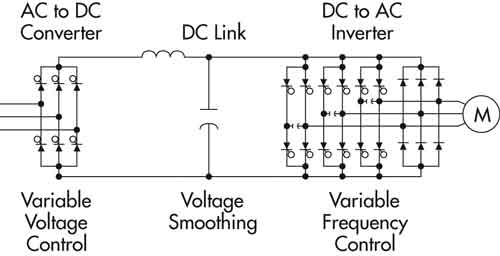
A DC bus in a VFD is the internal link between the rectifier and inverter sections. It stores and delivers filtered DC voltage, enabling efficient variable motor speed control.
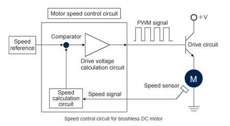
It serves as the intermediary stage that converts input voltage from AC to DC, allowing for precise control over output voltage and frequency. This process is crucial for driving induction motors efficiently and reliably, making the DC bus indispensable in industrial automation, HVAC systems, and other applications that require motor speed and torque adjustments. For electrical engineering and maintenance professionals, understanding the function and importance of the DC bus is vital for optimizing system performance, preventing faults, and ensuring energy efficiency in modern power systems. To understand how the DC bus supports speed regulation, see our guide on DC motor speed control and its relation to voltage and torque dynamics.
The DC bus voltage is fundamental to the operation of a VFD. This voltage is derived from the input voltage, typically calculated as 1.414 times the AC RMS line voltage. The DC bus plays a vital role in variable frequency drives, enabling their ability to vary motor speed with precision. For example, in a 480V AC system, the resulting DC bus voltage would approximate 678V DC. This multiplier arises from the conversion process and is pivotal for understanding the operational range of the VFD. Maintaining the appropriate DC bus voltage ensures the generation of a stable output voltage, which is critical for producing the smooth sine wave required to drive induction motors effectively. For a complete overview of VFD operation from input to output, read How does a VFD work, which explains the conversion stages in detail.
Think you know Motors and Drives? Take our quick, interactive quiz and test your knowledge in minutes.
Key components associated with the DC bus are designed to support its function and safeguard the system. Capacitors, for instance, are essential for filtering and smoothing the DC voltage, eliminating fluctuations that could otherwise disrupt motor performance. Additionally, dynamic braking systems—comprising braking resistors or choppers—manage excess energy generated during motor deceleration. By dissipating this energy as heat, these components prevent overvoltage conditions, protecting both the VFD and the connected motor. In HVAC systems, maintaining a stable DC bus voltage is critical to the performance of VFD HVAC applications.
In complex systems with multiple VFDs, a common DC bus configuration can be employed to optimize energy use. This setup enables energy sharing between drives, thereby enhancing the overall system efficiency. For instance, the braking energy from one motor can be repurposed to power another, reducing energy wastage and minimizing the need for external energy input. Such configurations are particularly advantageous in industrial environments where multiple motors operate concurrently. Learn how electric motor protection is integrated into VFD systems to prevent damage during electrical faults involving the DC bus.
Despite its robustness, the DC bus is not immune to operational challenges. Overvoltage and undervoltage faults are among the most common issues faced by VFDs. Overvoltage often occurs during rapid deceleration when regenerative energy from the motor exceeds the capacity of the dynamic braking system. Conversely, undervoltage may arise due to insufficient input voltage or fluctuations in line voltage. Proper monitoring and regular maintenance of the DC bus are crucial for ensuring reliable performance and preventing costly downtime. The importance of DC bus capacitors becomes clear when exploring electric motor efficiency and how power stability affects energy consumption.
Beyond its core function, the DC bus contributes to the overall efficiency and reliability of VFD-driven systems. By providing a stable DC link between the AC-to-DC and DC-to-AC conversion stages, the VFD enables precise control over motor speed and torque. This capability is invaluable in applications ranging from industrial automation to HVAC systems, where efficiency and precision are paramount. In multi-motor systems, a shared DC bus can optimize performance, similar to how synchronous motors coordinate speed and torque with high efficiency.
In summary, the DC bus in a VFD is more than just a conduit for power conversion. It is a sophisticated subsystem that plays a pivotal role in voltage regulation, energy management, and system protection. By understanding the dynamics of DC bus voltage, the roles of associated components such as capacitors and dynamic braking systems, and the advantages of common DC bus configurations, one can appreciate the technological sophistication underlying VFDs. Troubleshooting and maintaining the DC bus ensure that these systems continue to deliver optimal performance, driving modern industry forward with precision and reliability. The DC bus also contributes to VFD programming responsiveness—see our article on VFD programming for insight on how software interacts with hardware components.
Download our FREE Electrical Training Catalog and explore a full range of expert-led electrical training courses.

Advantages To Instructor-Led Training – Instructor-Led Course, Customized Training, Multiple Locations, Economical, CEU Credits, Course Discounts.
Request For QuotationWhether you would prefer Live Online or In-Person instruction, our electrical training courses can be tailored to meet your company's specific requirements and delivered to your employees in one location or at various locations.