Motors and Drives

Variable Frequency Drive HVAC Explained
Download Our FREE Motors and Drives Handbook
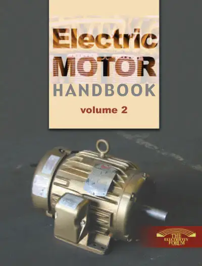
Electric Motors Handbook Vol. 2
This 144 page handbook will discuss motor management issues (protection, control and maintenance) from leading experts on electric motor selection, application, protection and control, maintenance and troubleshooting in modern electrical systems.
In this volume, we cover cutting-edge motor technologies, including advancements in brushless DC motors, synchronous motors, and integrated motor drives. With an emphasis on real-world applications, we examine how electric motors are being used in industries ranging from manufacturing and transportation to renewable energy and robotics. Additionally, this handbook provides critical insights into the evolving regulatory environment, safety standards, and sustainability trends impacting the electric motor sector.
By combining in-depth technical content with practical solutions, Electric Motors Handbook, Volume 2 serves as an essential resource for anyone involved in the design, maintenance, and management of electric motor systems. We hope this volume will enhance your understanding and empower you to leverage the full potential of electric motor technology in today's rapidly evolving landscape.
Latest Motors and Drives Articles
Learn How An Electric Motor Transforms Potential Energy Into Mechanical Energy
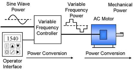
What Is a VFD?

How Does a VFD Work?
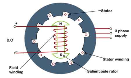
What is a Synchronous Motor? Explained
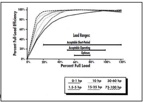
Electric Motor Efficiency