Lagging Power Factor and How to Correct It
By Colin P. Hurst, Associate Publisher
By Colin P. Hurst, Associate Publisher
Our customized live online or in‑person group training can be delivered to your staff at your location.

A lagging power factor occurs when current lags behind voltage, typically in inductive loads like motors or transformers. It reduces electrical efficiency, increases losses, and may incur utility penalties. Correction involves using capacitors or power factor correction equipment.
Power Quality Analysis Training
Request a Free Power Quality Training Quotation
Industrial electricians must understand how it arises, how it affects reactive energy flow, and how to correct it through proven engineering methods. Improving power factor (PF) not only boosts electrical efficiency but also helps facilities avoid penalties and reduce stress on equipment. A deep dive into power quality reveals the connection between harmonic distortion and PF in industrial settings.
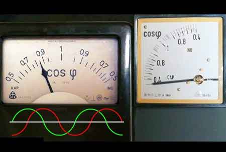
In AC systems, the phase relationship between voltage and current determines whether a system exhibits a lagging or leading PF. The classic mnemonic “ELI the ICE man” helps explain this: in inductive circuits (ELI), voltage leads current, producing a lag; in capacitive circuits (ICE), current leads voltage, creating a leading power factor. Most industrial equipment produces it, which must be managed to ensure efficient operations. To grasp the full picture of phase relationships, it is essential to understand the breakdown of leading vs. lagging power factor and their impact on reactive loads.
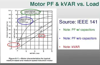
An inductive load—such as a motor or transformer—stores energy in magnetic fields. This delays the current relative to the voltage, creating a phase shift. The greater this phase angle, the lower the PF and the more inefficient the system becomes. This inefficiency leads to increased current demand, which strains distribution systems and results in higher utility charges.
Think you know Power Quality? Take our quick, interactive quiz and test your knowledge in minutes.
Reactive power (Q), measured in VARS, does no useful work but circulates within the system due to the voltage-current phase shift. It combines with real power (watts) to form apparent power (S), measured in VA. A high amount of Q increases total current, leading to voltage drops, energy losses, and reduced system efficiency. Read more about this in our What Is Reactive Power? article.
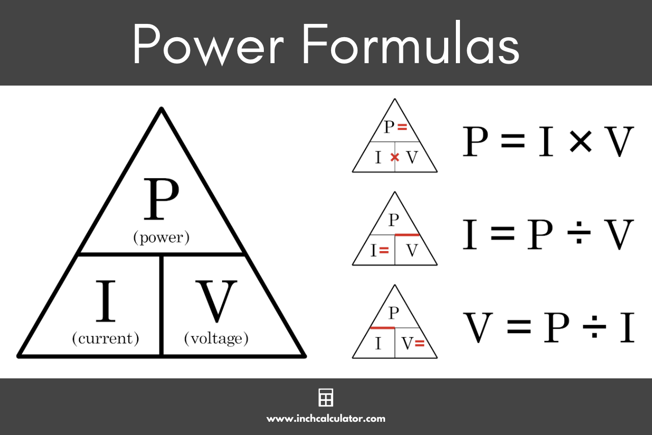
The power triangle visually illustrates the relationship between real power, Q, and S. As the angle between voltage and current increases (due to inductive loads), the triangle’s hypotenuse (S) grows larger relative to real power, signalling a worsening PF. Minimizing this angle brings the system closer to unity PF.
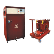
PFC involves adding capacitive loads that generate leading Q to cancel out lagging Q from inductive equipment. Correction can be done through:
Capacitor banks: Parallel-connected capacitors provide targeted compensation for inductive loads.
Automatic PFC units: These dynamically adjust compensation based on real-time conditions.
Synchronous condensers: Rotating machines that offer PFC and voltage regulation.
For a deep insight into Power Factor Correction Methods, read this article.
Non-linear loads, such as variable-frequency drives and electronic devices, introduce harmonics—distorted waveforms that worsen PF and increase reactive power (Q) demand. Harmonic filters or tuned capacitor banks are often required to mitigate their effects. This article on Harmonic Distortion and PQ explains the most important factors.
LPF increases current demand, leading to:
Elevated voltage drop
Greater conductor losses
Increased equipment heating
Shortened lifespan of transformers and cables
These issues collectively degrade system reliability and raise operational costs.
A lower PF intensifies voltage drop across electrical systems, particularly over long cable runs or with undersized conductors. This can cause sensitive equipment to malfunction or degrade over time. Read all about Voltage Drop and Its Effects in this article.
It is caused by inductive loads, such as motors, transformers, and fluorescent lighting, where current lags behind voltage due to the storage of magnetic energy.
It increases current demand, causing higher energy losses, greater voltage drop, equipment overheating, and potential utility penalties.
It can be corrected by installing capacitors, synchronous condensers, or automatic PFC equipment to balance Q.
It increases current demand, resulting in energy losses and higher utility bills. It can degrade equipment, increase heat, and trigger utility penalties in industrial systems.
The most common method is installing PFC capacitors, which introduce leading Q to balance the system. Synchronous condensers and automatic PFC systems are also used in dynamic environments.
Addressing it is essential in industrial settings because it directly affects energy efficiency and operational costs. With a lagging PF, facilities may incur additional charges from utility providers and risk overloading their infrastructure due to higher current demands. By improving PF, companies can reduce these costs, enhance system reliability, minimize equipment wear and tear, and contribute to more sustainable energy usage.
Understanding it is crucial for optimizing electrical systems, especially in industrial settings with prevalent inductive loads. By implementing PF correction techniques, such as installing capacitor banks, electricians can reduce energy waste, lower costs, and enhance the overall efficiency and reliability of the distribution system. For a practical example, learn how a power factor meter helps monitor and improve performance in systems affected by a lagging PF.
Download our FREE Electrical Training Catalog and explore a full range of expert-led electrical training courses.

Advantages To Instructor-Led Training – Instructor-Led Course, Customized Training, Multiple Locations, Economical, CEU Credits, Course Discounts.
Request For QuotationWhether you would prefer Live Online or In-Person instruction, our electrical training courses can be tailored to meet your company's specific requirements and delivered to your employees in one location or at various locations.