Grounding Electrode
By James Lund, Galvan Industries

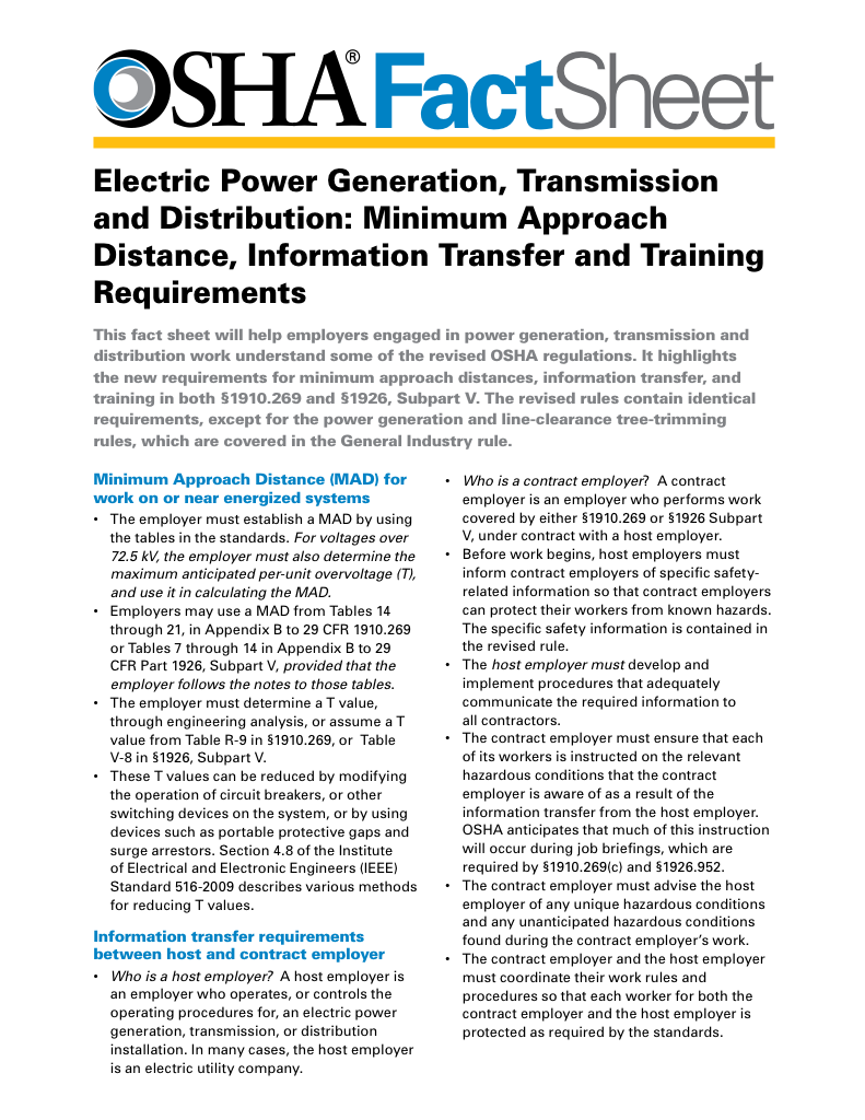
Download Our OSHA 3873 Fact Sheet – Minimum Approach Distance and Training Requirements

- Calculate MAD using voltage and overvoltage values
- Ensure proper communication between host and contract employers
- Meet OSHA training requirements for qualified electrical workers
A grounding electrode is a conductive element, such as a metal rod or plate, that connects electrical systems to the earth. It safely disperses fault currents, stabilizes voltage levels, and is essential for electrical safety and code compliance.
What is a Grounding Electrode?
A grounding electrode is a vital component of any electrical system. It is a conductive element, such as a metal rod, plate, or concrete-encased rebar, that connects the electrical system to the earth.
✅ Connects electrical systems to earth to safely discharge fault currents
✅ Helps stabilize voltage and prevent equipment damage
✅ Required for electrical code compliance and personal safety
This connection safely dissipates fault currents, stabilizes voltage levels, and protects both equipment and personnel. Proper grounding is not only essential for electrical safety but is also mandated by national electrical coA grounding electrode is a vital component of any electrical system. It is a conductive element, such as a metal rod, plate, or concrete-encased rebar, that connects the electrical system to the earth. des such as NEC 250.52 and CSA standards. To better understand the broader framework behind safe grounding practices, see our overview of electrical grounding principles.
NEC-Approved Grounding Electrode Types
The National Electrical Code (NEC) outlines various types of grounding electrodes approved for use in electrical installations. These include metal underground water pipes, building steel embedded in concrete, concrete-encased electrodes (commonly referred to as Ufer grounds), ground rings, and rods or pipes driven into the earth. These different electrode types are chosen based on the installation environment and desired longevity.
-
Metal water pipes must be in contact with earth for at least 10 feet.
-
Concrete-encased electrodes use rebar or copper conductor at least 20 feet in length.
-
Ground rods and pipes must be at least 8 feet long and meet diameter standards.
NEC standards such as grounding and bonding requirements are essential for selecting compliant materials and configurations.
Sign Up for Electricity Forum’s Overhead T&D Newsletter
Stay informed with our FREE Overhead T&D Newsletter — get the latest news, breakthrough technologies, and expert insights, delivered straight to your inbox.
Grounding Electrode Conductor (GEC) Sizing and Function
Beyond the electrode itself, the grounding electrode conductor (GEC) plays a critical role in the overall grounding system. The GEC connects the electrode to the main service panel or system grounding point. Sizing of the GEC is determined by the largest ungrounded service-entrance conductor, as outlined in NEC Table 250.66. The conductor must be adequately sized to carry fault current safely without excessive heating or damage.
-
Copper GECs typically range from 8 AWG to 3/0 AWG, depending on the system size.
-
Aluminum conductors may be used but require larger sizes due to lower conductivity.
-
For rod, pipe, or plate electrodes, the maximum required GEC size is 6 AWG copper.
Learn how proper grounding electrode conductor sizing ensures the safe dissipation of fault currents in compliance with NEC 250.66.
Best Practices for Ground Rod Installation
Installation best practices ensure that the electrode system performs as intended. Ground rods must be driven at least 8 feet into the soil, and if multiple rods are required, they must be spaced at least 6 feet apart. Soil conditions, moisture levels, and temperature significantly impact the effectiveness of grounding systems, making proper placement and testing crucial.
-
Electrodes should be installed vertically, where possible, for better conductivity.
-
Ground resistance testing should confirm values below 25 ohms for single rods.
-
Supplemental electrodes may be required to meet code if resistance exceeds this limit.
For deeper insight into how grounding integrates into entire system design, explore our guide on grounding systems and layout strategies.
Soil Resistivity and Its Impact on Grounding System Performance
Soil composition is a critical factor in determining the effectiveness of a grounding electrode. High-resistivity soils such as sand or gravel reduce system reliability. In such cases, chemical ground rods or deeper electrode systems may be required. Soil resistivity testing, using methods like the Wenner or Schlumberger test, can guide engineering decisions.
-
Moist, loamy soil provides the best conductivity.
-
Dry or frozen soil increases resistance significantly.
-
Chemical rods are useful in rocky or high-resistance soils.
If you're working in areas with soil that inhibits conductivity, high-resistance grounding methods may be necessary to maintain performance.
Comparing Types of Ground Rods and Their Applications
There are several types of ground rods available, each with unique properties and applications. Hot-dip galvanized rods are cost-effective and provide reliable performance in many environments. Copper-clad rods, while more expensive, offer enhanced corrosion resistance. Stainless steel and chemical ground rods are typically reserved for specialized applications with extreme soil conditions or longevity requirements.
-
Galvanized rods are economical and meet ASTM A-123 or B-633 standards.
-
Copper-clad rods meet UL 467 and offer superior corrosion protection.
-
Stainless steel and chemical rods are high-cost but high-performance options.
For clarification on the term itself, see our complete definition of electrical grounding and how it applies across systems.
Ensuring Electrical Code Compliance
Code compliance and product specification are essential aspects of grounding design. All rods and connectors must meet standards such as UL 467, ASTM A-123, or CSA. Installers must ensure that products ordered match specifications to avoid liabilities and safety risks. Dissimilar metals should be avoided to prevent galvanic corrosion, which can reduce system lifespan.
-
Ensure product labeling matches listed standards.
-
Avoid mixing copper and galvanized steel in close proximity.
-
Confirm resistance-to-ground targets as part of final inspection.
Grounding System Design for Safety and Reliability
In conclusion, designing and installing an effective grounding electrode system requires a comprehensive understanding of codes, soil science, material properties, and safety considerations. Proper selection and installation of grounding components not only ensure regulatory compliance but also promote system reliability and long-term protection of assets and personnel. Additional techniques and requirements are explained in our article on understanding electrical grounding, which connects grounding electrodes to broader system safety.
Test Your Knowledge About Overhead T&D!
Think you know Overhead T&D? Take our quick, interactive quiz and test your knowledge in minutes.
- Instantly see your results and score
- Identify strengths and areas for improvement
- Challenge yourself on real-world electrical topics


