What is Current Electricity?
By R.W. Hurst, Editor
Current electricity is the flow of electric charge through a conductor, measured in amperes and given by the relationship I = V/R between voltage, resistance, and current. It describes how electrons move in circuits, including AC and DC behavior, enabling circuit operation.
Current electricity is the continuous movement of electric charge through a conductive path within a closed circuit, driven by a voltage difference that creates an electric field and causes electrons to move. The rate of this movement is measured in amperes and depends on the balance between applied voltage and circuit resistance, expressed by Ohm’s Law as I = V / R. In this context, current electricity refers to charge in motion within circuits, rather than the broader concept of electric current as a general physical quantity, and is distinct from static electricity, where charge accumulates rather than flows.
What is current electricity in circuits
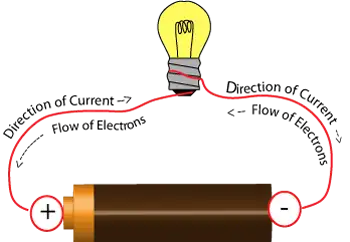
In electrical circuits, current electricity represents the movement of electrons through a complete path. When a voltage source, such as a battery or generator, applies a potential difference, it creates the conditions required for charge to move through conductors.
Current only exists when the circuit is closed. If the path is interrupted, the charge's motion stops immediately. This principle explains how switches control operation and how protective devices interrupt current during fault conditions.
The relationship among voltage, resistance, and current is defined in What Is Ohm’s Law, which establishes the governing relationship used in circuit analysis.
Alternating current vs direct current
Current electricity can behave differently depending on how the charge moves over time.
Alternating current periodically reverses direction, typically following a repeating waveform. This characteristic allows efficient transmission across electrical networks. Further detail is provided in What Is Alternating Current.
Direct current flows in a single direction with constant polarity. It is commonly used in batteries, electronics, and control circuits. This behavior is explained in Direct Current.
These describe patterns of current flow rather than separate forms of electricity.
Measurement of current electricity
Current is measured using instruments such as ammeters and is expressed in amperes. One ampere represents one coulomb of charge passing a point in one second.
Accurate measurement of current is essential for understanding circuit behavior and maintaining safe operation. Equipment is designed to operate within defined current limits to prevent overheating or failure. Additional detail is available in What Is An Ampere.
Relationship between current, voltage, and resistance
Current exists as part of a relationship with voltage and resistance in every circuit.
Voltage provides the force that drives the movement of charge, while resistance limits that movement. The balance between these quantities determines how much current flows through a conductor.
This interaction is central to electrical behavior and is further explained in Voltage and Electrical Resistance.
Practical meaning of current electricity
In practical terms, current electricity is the movement of charge that allows electrical systems to operate. It enables devices such as motors, lighting systems, and electronic equipment to function.
The presence, magnitude, and direction of current determine how circuits behave under normal conditions and during faults. Understanding current flow is essential for interpreting system performance and maintaining reliable operation.
A broader foundational context is introduced in What Is Electricity.
Related Articles
