What is a Watt-hour?


What is a Watt-hour

A watt-hour (Wh) is a unit of energy equal to using one watt of power for one hour. It measures how much electricity is consumed over time and is commonly used to track energy use on utility bills.

Understanding watt-hours is important because it links electrical power (watts) and time (hours) to show the total amount of energy used. To better understand the foundation of electrical energy, see our guide on What is Electricity?


Watt-Hour vs Watt: What's the Difference?

Although they sound similar, watts and watt-hours measure different concepts.

  • Watt (W) measures the rate of energy use — how fast energy is being consumed at a given moment.

  • Watt-hour (Wh) measures the amount of energy used over a period of time.

An easy way to understand this is by comparing it to driving a car:

  • Speed (miles per hour) shows how fast you are travelling.

  • Distance (miles) shows how far you have travelled in total.

Watt-hours represent the total energy consumption over a period, not just the instantaneous rate. You can also explore the relationship between electrical flow and circuits in What is an Electrical Circuit?


How Watt-Hours Are Calculated

Calculating watt-hours is straightforward. It involves multiplying the power rating of a device by the length of time it operates.
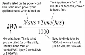
The basic formula is:

Energy (Wh) = Power (W) × Time (h)

This illustrates this relationship, showing how steady power over time yields a predictable amount of energy consumed, measured in watt-hours. For a deeper look at electrical power itself, see What is a Watt? Electricity Explained


Real-World Examples of Watt-Hour Consumption

To better understand how watt-hours work, it is helpful to examine simple examples. Different devices consume varying amounts of energy based on their wattage and the duration of their operation. Even small variations in usage time or power level can significantly affect total energy consumption.

Here are a few everyday examples to illustrate how watt-hours accumulate:

  • A 60-watt lightbulb uses 60 watt-hours (Wh) when it runs for one hour.

  • A 100-watt bulb uses 1 Wh in about 36 seconds.

  • A 6-watt Christmas tree bulb would take 10 minutes to consume 1 Wh.

These examples demonstrate how devices with different power ratings achieve the same energy consumption when allowed to operate for sufficient periods. Measuring energy usage often involves calculating current and resistance, which you can learn more about in What is Electrical Resistance?


Understanding Energy Consumption Over Time

In many cases, devices don’t consume energy at a steady rate. Power use can change over time, rising and falling depending on the device’s function. Figure 2-6 provides two examples of devices that each consume exactly 1 watt-hour of energy but in different ways — one at a steady rate and one with variable consumption.

Here's how the two devices compare:

  • Device A draws a constant 60 watts and uses 1 Wh of energy in exactly 1 minute.

  • Device B starts at 0 watts and increases its power draw linearly up to 100 watts, still consuming exactly 1 Wh of energy in total.

For Device B, the energy consumed is determined by finding the area under the curve in the power vs time graph.
Since the shape is a triangle, the area is calculated as:

Area = ½ × base × height

In this case:

  • Base = 0.02 hours (72 seconds)

  • Height = 100 watts

  • Energy = ½ × 100 × 0.02 = 1 Wh

This highlights an important principle: even when a device's power draw varies, you can still calculate total energy usage accurately by analyzing the total area under its power curve.

It’s also critical to remember that for watt-hours, you must multiply watts by hours. Using minutes or seconds without converting will result in incorrect units.


Fig. 2-6. Two hypothetical devices that consume 1 Wh of energy.


Measuring Household Energy Usage

While it’s easy to calculate energy consumption for a single device, it becomes more complex when considering an entire household's energy profile over a day.
Homes have highly variable power consumption patterns, influenced by activities like cooking, heating, and running appliances at different times.

Figure 2-7 shows an example of a typical home’s power usage throughout a 24-hour period. The curve rises and falls based on when devices are active, and the shape can be quite complex. Saving energy at home starts with understanding how devices consume power; see How to Save Electricity

Instead of manually calculating the area under such an irregular curve to find the total watt-hours used, electric utilities rely on electric meters. These devices continuously record cumulative energy consumption in kilowatt-hours (kWh).

Each month, the utility company reads the meter, subtracts the previous reading, and bills the customer for the total energy consumed.
This system enables accurate tracking of energy use without the need for complex mathematical calculations.


Fig. 2-7. Graph showing the amount of power consumed by a hypothetical household, as a function of the time of day.


Watt-Hours vs Kilowatt-Hours

Both watt-hours and kilowatt-hours measure the same thing — total energy used — but kilowatt-hours are simply a larger unit for convenience. In daily life, we usually deal with thousands of watt-hours, making kilowatt-hours more practical.

Here’s the relationship:

  • 1 kilowatt-hour (kWh) = 1,000 watt-hours (Wh)

To see how this applies, consider a common household appliance:

  • A refrigerator operating at 150 watts for 24 hours consumes:

    • 150 W × 24 h = 3,600 Wh = 3.6 kWh

Understanding the connection between watt-hours and kilowatt-hours is helpful when reviewing your utility bill or managing your overall energy usage.

Watt-hours are essential for understanding total energy consumption. Whether power usage is steady or variable, calculating watt-hours provides a consistent and accurate measure of energy used over time.
Real-world examples — from simple light bulbs to complex household systems — demonstrate that, regardless of the situation, watt-hours provide a clear way to track and manage electricity usage. 

By knowing how to measure and interpret watt-hours and kilowatt-hours, you can make more informed decisions about energy consumption, efficiency, and cost savings. For a broader understanding of how energy ties into everyday systems, visit What is Energy? Electricity Explained


Related Articles


Related News

Types of Capacitors

The types of capacitors vary by design and application, including ceramic, electrolytic, film, and supercapacitors. Each offers unique benefits for electronics, power supply circuits, energy storage, and filtering needs.


What are the types of capacitors?

The types of capacitors are classified by material, function, and performance, serving vital roles in electronics and electrical systems.

✅ Ceramic, electrolytic, film, and supercapacitors used in diverse applications

✅ Store and regulate electrical energy in circuits, power systems, and devices

✅ Enable filtering, smoothing, and energy storage for stable performance


There are various types of capacitors. They are electronic components of electric filters and tuned circuits that store and release electrical energy. They consist of two conductive plates separated by a dielectric material. When a voltage is applied across the plates, an electric field is created between them, and an electrical charge accumulates on the plates. It represents the distance between the plates. The capacitance of a polarized capacitor is a measure of its ability to store electrical charge. To fully understand how capacitance works in different circuits, it is essential to study the various types and their dielectric materials.

These are widely used in electronic circuits, performing various functions such as filtering, smoothing, coupling, and timing. They can be found in everything from simple electronic devices like flashlights and radios to complex systems such as computers and spacecraft. A solid foundation in basic electricity helps explain why capacitors store and release energy depending on voltage and plate separation.

They come in many different types and sizes, each with unique properties that make them suitable for other applications. The most common types include ceramic, electrolytic, tantalum, film, and supercapacitors.

Engineers often compare capacitance in parallel with capacitance in series to determine how different capacitor arrangements affect circuit behavior.


Schematic symbols for a fixed and variable capacitor.


Ceramic

Ceramic capacitors use ceramic as their dielectric material and are ideal for high-frequency applications. They are available in different types, such as class 1 and class 2. Class 1 caps are used in circuits that require high precision and stability, while class 2 types of capacitors are used in circuits that require high capacitance values. In addition, ceramic caps are commonly used in decoupling, bypassing, and coupling applications.


Electrolytic

Electrolytic caps use an electrolyte as their dielectric material and are polarized. They are known for their high capacitance values and are commonly used in power supply circuits. There are two types of electrolytic caps: aluminum electrolytic caps and tantalum electrolytic caps. Aluminum electrolytic types of capacitors are inexpensive and have a high capacitance value, while tantalum electrolytic caps have higher stability and lower leakage current. Electrolytic caps are commonly used in DC blocking, coupling, and filtering applications.


Film

Film capacitors use a thin plastic or polymer layer as their dielectric material. They are known for their high stability and low losses, which are ideal for high-frequency applications. Film caps come in different types, such as metalized and film/foil, each with unique characteristics. Metalized film caps are used in circuits that require high capacitance values, while film/foil caps are used in circuits that require high precision and stability. Film caps are commonly used in decoupling, coupling, and filtering applications.


Tantalum

Tantalum capacitors are polarized caps that use tantalum metal as their anode. They are known for their high stability and are commonly used in low-voltage applications. Tantalum caps are available in tantalum foil caps and tantalum polymer caps. Tantalum foil caps are known for their high reliability. They are commonly used in aerospace and military applications, while tantalum polymer caps are known for their high capacitance values and low ESR, making them ideal for portable devices.


Mica

Silver mica capacitors use mica as their dielectric material and are known for their high precision, low losses, and excellent stability. They are used in various RF circuits, filters, and timing applications. Mica caps are available in different types, such as silver mica caps and ceramic mica caps. Silver mica caps are known for their high precision and stability. They are commonly used in RF circuits, while ceramic mica caps are known for their high capacitance values and low cost.


Oil


Variable Types

Variable caps are used in electronic circuits where the capacitance value needs to be adjusted. They consist of two conductive plates separated by an air gap, and the capacitance value can be changed by adjusting the distance between the plates. For example, variable caps are commonly used in radio tuning circuits and frequency control circuits.


Supercapacitors

Supercapacitors, also known as ultracapacitors, are a type of capacitor that has a higher energy storage capacity than other types. They are commonly used in applications where high power delivery is needed, such as in electric vehicles and renewable energy systems. They have a higher energy density than electrolytic caps and can be charged and discharged quickly, making them ideal for applications with a quick power boost.


Paper

Paper caps use paper as their dielectric material and are known for their high stability and low losses. Therefore, they are commonly used in filters, timing, and coupling applications. Paper caps are available in different types, such as oil-impregnated paper caps and metalized paper caps. Oil-impregnated paper caps are known for their high stability. Therefore, they are commonly used in high-voltage applications, while metalized paper caps are known for their high capacitance values and low cost.


Power

Power capacitors like power electronics and motor drives are designed for high voltage and high current applications. They are available in different types, such as film and electrolytic, each with unique characteristics. Power caps are known for their high reliability and low losses, making them ideal for high-power applications.


Frequently Asked Questions


What is an electrolytic capacitor, and how is it used?

An electrolytic capacitor is a type of capacitor that uses an electrolyte to achieve a more considerable capacitance value than other types. They are commonly used in power supply circuits due to their high capacitance values and ability to handle high voltages. Electrolytic caps have a polarized design and need to be installed with the correct polarity. Otherwise, they can fail or even explode due to the working voltage ratings. The unit of capacitance, measured in farads, is explained in more detail on our unit of capacitance page, along with practical examples. When comparing passive components, it is helpful to explore both the types of resistors and the types of caps to see how they complement each other in circuits.


How do ceramic capacitors differ?

Ceramic capacitors are a type of capacitor that uses a ceramic material as the dielectric. They are known for their high stability, low cost, and low leakage current. They can also operate at high temperatures due to their insulating layer.

What is a tantalum capacitor, and what are its advantages and disadvantages?

A tantalum capacitor is an electrolytic capacitor that uses tantalum as the anode material. They have a high capacitance per volume ratio and are commonly used in electronic circuits where space is limited. Tantalum ones also have a high level of stability and low leakage current. Additionally, they can operate at high temperatures due to the oxidized layer on the surface. However, they are more expensive than other types and can be sensitive to voltage spikes, which can cause them to fail.


What are film capacitors, and how are they used in electronic circuits?

Film capacitors are a type of capacitor that uses a thin film as the dielectric. They are known for their stability, low leakage current, and ability to operate at high frequencies. Film caps are commonly used in high-precision electronic circuits, such as audio equipment and signal processing circuits. The distance between the plates in a film capacitor represents the capacitance value.


What are the advantages and disadvantages of using supercapacitors?

Supercapacitors, also known as ultra, are a type of capacitor that has a much higher capacitance value than other types. As a result, they can store and release energy quickly and can handle many charge and discharge cycles. Additionally, they can operate at high temperatures. However, supercapacitors have a lower energy density than other types of energy storage devices, such as batteries, and can be more expensive due to their large capacitance.


How do variable capacitors differ from fixed capacitors?

Variable capacitors have a capacitance value that can be adjusted. They have commonly used in radio frequency (RF) circuits where the capacitance must be tuned to a specific frequency. Unlike fixed ones, variable ones have a moving plate that can be adjusted to change the capacitance value. They can also operate at high temperatures due to their insulating layer.


Related Articles


View more

How Is Electricity Generated?

It is produced by converting various energy sources, such as fossil fuels, nuclear, solar, wind, or hydro, into electrical energy using turbines and generators. These systems harness mechanical or chemical energy and transform it into usable power.


How Is Electricity Generated?

✅ Converts energy sources like coal, gas, wind, or sunlight into power

✅ Uses generators driven by turbines to create electrical current

✅ Supports global power grids and industrial, commercial, and residential use


Understanding Electricity Generation

Electricity generation is the lifeblood of modern civilization, powering homes, industries, hospitals, transportation systems, and digital infrastructure. But behind the flip of a switch lies a vast and complex process that transforms raw energy into electrical power. At its core, electricity is generated by converting various forms of energy—mechanical, thermal, chemical, or radiant—into a flow of electric charge through systems engineered for efficiency and reliability.

Understanding the role of voltage is essential in this process, as it determines the electrical pressure that drives current through circuits.

According to the Energy Information Administration, the United States relies on a diverse mix of technologies to produce electric power, including fossil fuels, nuclear power, and renewables. In recent years, the rapid growth of solar photovoltaic systems and the widespread deployment of wind turbines have significantly increased the share of clean energy in the national grid. These renewable systems often use turbines to generate electricity by converting natural energy sources—sunlight and wind—into mechanical motion and ultimately electrical power. This transition reflects broader efforts to reduce emissions while meeting rising electric power demand.


How Power Generation Works

Most electricity around the world is produced using turbines and generators. These devices are typically housed in large-scale power plants. The process begins with an energy source—such as fossil fuels, nuclear reactions, or renewable inputs like water, wind, or sunlight—which is used to create movement. This movement, in turn, drives a turbine, which spins a shaft connected to a generator. Inside the generator, magnetic fields rotate around conductive coils, inducing a voltage and producing alternating current (AC) electricity. This method, known as electromagnetic induction, is the fundamental mechanism by which nearly all electric power is made.

In designing and maintaining electrical systems, engineers must also consider voltage drop, which can reduce efficiency and power quality. You can evaluate system losses using our interactive voltage drop calculator, and better understand the math behind it using the voltage drop formula.


Energy Sources Used in Power Production

Steam turbines remain the dominant technology in global energy production. These are especially common in plants that burn coal, natural gas, or biomass, or that rely on nuclear fission. In a typical thermal power plant, water is heated to create high-pressure steam, which spins the turbine blades. In nuclear facilities, this steam is generated by the immense heat released when uranium atoms are split. While highly efficient, these systems face environmental and safety concerns—greenhouse gas emissions from fossil fuels, radioactive waste and accident risk from nuclear power.

Power quality in these plants can be impacted by voltage sag, which occurs when systems experience a temporary drop in electrical pressure, often due to sudden large loads or faults. Managing such variations is crucial to stable output.


The Rise of Renewable Energy in Electricity Generation

Alongside these large-scale thermal technologies, renewable sources have grown significantly. Hydroelectric power harnesses the kinetic energy of falling or flowing water, typically from a dam, to spin turbines. Wind energy captures the movement of air through large blades connected to horizontal-axis turbines. Solar power generates electricity in two distinct ways: photovoltaic cells convert sunlight directly into electric power using semiconductors, while solar thermal plants concentrate sunlight to heat fluids and produce steam. Geothermal systems tap into the Earth’s internal heat to generate steam directly or via heat exchangers.

These renewable systems offer major advantages in terms of sustainability and environmental impact. They produce no direct emissions and rely on natural, often abundant energy flows. However, they also face limitations. Solar and wind power are intermittent, meaning their output fluctuates with weather and time of day. Hydropower and geothermal are geographically constrained, only viable in certain regions. Despite these challenges, renewables now account for a growing share of global electricity generation and play a central role in efforts to decarbonize the energy sector.

In areas where water and electricity coexist—such as hydroelectric plants—understanding the risks associated with water and electricity is critical to ensure operational safety and prevent electrocution hazards.


Generators and Turbines: The Heart of Electricity Generation

Generators themselves are marvels of electromechanical engineering. They convert rotational kinetic energy into electrical energy through a system of magnets and copper windings. Their efficiency, durability, and capacity to synchronize with the grid are critical to a stable electric power supply. In large plants, multiple generators operate in parallel, contributing to a vast, interconnected grid that balances supply and demand in real-time.

Turbines, powered by steam, water, gas, or wind, generate the rotational force needed to drive the generator. Their design and performance have a significant impact on the overall efficiency and output of the plant. Measuring output accurately requires devices like a watthour meter or wattmeters, which are standard tools in generation stations.

Technicians often use formulas such as Watt’s Law to determine power consumption and verify performance. Understanding what ammeters measure also plays a role in monitoring electrical current flowing through generator systems.

Related Articles


View more

What is Voltage?

Voltage is the electrical potential difference between two points, providing the force that moves current through conductors. It expresses energy per charge, powering devices, controlling circuits, and ensuring efficient and safe operation of electrical and electronic systems.


What is Voltage?

Voltage is the electric potential difference, the work done per unit charge (Joules per Coulomb). It: 

✅ Is the difference in electric potential energy between two points in a circuit.

✅ Represents the force that pushes electric current through conductors.

✅ It is measured in volts (V), and it is essential for power distribution and electrical safety.

To comprehend the concept of what is voltage, it is essential to understand its fundamental principles. Analogies make this invisible force easier to picture. One of the most common is the water pressure analogy: just as higher water pressure pushes water through pipes more forcefully, higher voltage pushes electric charges through a circuit. A strong grasp of voltage begins with the fundamentals of electricity fundamentals, which explain how current, resistance, and power interact in circuits.

Another way to imagine what is voltage is as a hill of potential energy. A ball placed at the top of a hill naturally rolls downward under gravity. The steeper the hill, the more energy is available to move the ball. Likewise, a higher voltage means more energy is available per charge to move electrons in a circuit.

A third analogy is the pump in a water system. A pump creates pressure, forcing water to move through pipes. Similarly, a battery or generator functions as an electrical pump, supplying the energy that drives electrons through conductors. Without this push, charges would remain in place and no current would flow.

Together, these analogies—water pressure, potential energy hill, and pump—show how voltage acts as the essential driving force, the “electrical pressure” that enables circuits to function and devices to operate. Since voltage and Current are inseparable, Ohm’s Law shows how resistance influences the flow of electricity in every system.

These analogies help us visualize voltage as pressure or stored energy, but in physics, voltage has a precise definition. It is the work done per unit charge to move an electric charge from one point to another. Mathematically, this is expressed as:

V = W / q

where V is voltage (in volts), W is the work or energy (in joules), and q is the charge (in coulombs). This equation shows that one volt equals one joule of energy per coulomb of charge.

In circuit analysis, voltage is also described through Ohm’s Law, which relates it to current and resistance:

V = I × R

where I is current (in amperes) and R is resistance (in ohms). This simple but powerful formula explains how voltage, current, and resistance interact in every electrical system.

Italian physicist Alessandro Volta played a crucial role in discovering and understanding V. The unit of voltage, the volt (V), is named in his honor. V is measured in volts, and the process of measuring V typically involves a device called a voltmeter. In an electrical circuit, the V difference between two points determines the energy required to move a charge, specifically one coulomb of charge, between those points. The history of voltage is closely tied to the History of Electricity, where discoveries by pioneers like Volta and Franklin have shaped modern science.

An electric potential difference between two points produces an electric field, represented by electric lines of flux (Fig. 1). There is always a pole that is relatively positive, with fewer electrons, and one that is relatively negative, with more electrons. The positive pole does not necessarily have a deficiency of electrons compared with neutral objects, and the negative pole might not have a surplus of electrons compared with neutral objects. But there's always a difference in charge between the two poles. So the negative pole always has more electrons than the positive pole.


Fig 1. Electric lines of flux always exist near poles of electric charge.


The abbreviation for voltage measurement is V. Sometimes, smaller units are used. For example, the millivolt (mV) is equal to a thousandth (0.001) of a volt. The microvolt (uV) is equal to a millionth (0.000001) of a volt. And it is sometimes necessary to use units much larger than one volt. For example, one kilovolt (kV) is equal to one thousand volts (1,000). One megavolt (MV) is equal to one million volts (1,000,000) or one thousand kilovolts. When comparing supply types, the distinction between Direct Current and AC vs DC shows why standardized voltage systems are essential worldwide.

The concept of what is voltage is closely related to electromotive force (EMF), which is the energy source that drives electrons to flow through a circuit. A chemical battery is a common example of a voltage source that generates EMF. The negatively charged electrons in the battery are compelled to move toward the positive terminal, creating an electric current.

In power distribution, three-phase electricity and 3 Phase Power demonstrate how higher voltages improve efficiency and reliability.

Voltage is a fundamental concept in electrical and electronic systems, as it influences the behavior of circuits and devices. One of the most important relationships involving V is Ohm's Law, which describes the connection between voltage, current, and resistance in an electrical circuit. For example, Ohm's Law states that the V across a resistor is equal to the product of the current flowing through it and the resistance of the resistor. 

The voltage dropped across components in a circuit is critical when designing or analyzing electrical systems. Voltage drop occurs when the circuit components, such as resistors, capacitors, and inductors, partially consume the V source's energy. This phenomenon is a crucial aspect of circuit analysis, as it helps determine a system's power distribution and efficiency. Potential energy is defined as the work required to move a unit of charge from different points in an electric dc circuit in a static electric field.  Engineers often analyze Voltage Drop to evaluate circuit performance, alongside concepts like Electrical Resistance.

Voltage levels are standardized in both household and industrial applications to ensure the safe and efficient operation of electrical equipment. In residential settings, common voltage levels range from 110 to 240 volts, depending on the country. Industrial applications often utilize higher voltages, ranging from several kilovolts to tens of kilovolts, to transmit electrical energy over long distances with minimal losses.

Another important distinction in the realm of voltage is the difference between alternating current (AC) and direct current (DC). AC alternates periodically, whereas DC maintains a constant direction. AC is the standard for most household and industrial applications, as it can be easily transformed to different voltage levels and is more efficient for long-distance transmission. DC voltage, on the other hand, is often used in batteries and electronic devices.

Voltage is the driving force behind the flow of charge carriers in electrical circuits. It is essential for understanding the behavior of circuits and the relationship between voltage, current, and resistance, as described by Ohm's Law. The importance of V levels in household and industrial applications, as well as the significance of voltage drop in circuit analysis, cannot be overstated. Finally, the distinction between AC and DC voltage is critical for the safe and efficient operation of electrical systems in various contexts.

By incorporating these concepts into our understanding of voltage, we gain valuable insight into the world of electricity and electronics. From the pioneering work of Alessandro Volta to the modern applications of voltage in our daily lives, it is clear that voltage will continue to play a crucial role in the development and advancement of technology. Foundational principles such as Amperes Law and the Biot Savart Law complement voltage by describing how currents and magnetic fields interact.


Related Articles


View more

Electricity How it Works

Electricity How It Works explains electron flow, voltage, current, resistance, and power in circuits, from generation to distribution, covering AC/DC systems, Ohm's law, conductors, semiconductors, transformers, and energy conversion efficiency and safety.


The Science Behind How Electricity Works

Electricity How It Works - This is a very common question. It can best be explained by stating this way: Single-phase electricity is what you have in your house. You generally talk about household electrical service as single-phase, 120-volt AC service. If you use an oscilloscope and look at the power found at a normal wall-plate outlet in your house, what you will find is that the power at the wall plate looks like a sine wave, and that wave oscillates between -170 volts and 170 volts (the peaks are indeed at 170 volts; it is the effective (rms) voltage that is 120 volts). The rate of oscillation for the sine wave is 60 cycles per second. Oscillating power like this is generally referred to as AC, or alternating current. The alternative to AC is DC, or direct current. Batteries produce DC: A steady stream of electrons flows in one direction only, from the negative to the positive terminal of the battery.

For a refresher on fundamentals, the overview at what is electricity explains charge, current, and voltage in practical terms.

AC has at least three advantages over DC in an electricity power distribution grid:

1. Large electricity generators happen to generate AC naturally, so conversion to DC would involve an extra step.
2. Electrical Transformers must have alternating current to operate, and we will see that the power distribution grid depends on transformers. 
3. It is easy to convert AC to DC but expensive to convert DC to AC, so if you were going to pick one or the other AC would be the better choice.

To connect these advantages to real-world practice, the primer on basic electricity clarifies AC versus DC behavior, impedance, and safety basics.

The electricity generating plant, therefore, produces AC. For a deeper look at how rotating machines induce AC, see the overview of electricity generators and their role in utility-scale plants.


Electricity How it Works in The Power Plant: Three-phase Power

If you want a quick walkthrough from generation to loads, this guide on how electricity works ties the concepts together before we examine three-phase specifics.

The power plant produces three different phases of AC power simultaneously, and the three phases are offset 120 degrees from each other. There are four wires coming out of every power plant: the three phases plus a neutral or ground common to all three. If you were to look at the three phases on a graph, they would look like this relative to ground:

A concise visual explainer on three-phase electricity shows how 120-degree phase offsets create balanced currents in feeders.

Electricity How It Works - There is nothing magical about three-phase power. It is simply three single phases synchronized and offset by 120 degrees. For wiring diagrams and common configurations, explore 3-phase power examples used across industrial facilities.

Why three phases? Why not one or two or four? In 1-phase and 2-phase electricity, there are 120 moments per second when a sine wave is crossing zero volts. In 3-phase power, at any given moment one of the three phases is nearing a peak. High-power 3-phase motors (used in industrial applications) and things like 3-phase welding equipment therefore have even power output. Four phases would not significantly improve things but would add a fourth wire, so 3-phase is the natural settling point.

Practical comparisons of motor torque ripple and line loading in 3-phase electricity help illustrate why three conductors strike the best balance.

And what about this "ground," as mentioned above? The power company essentially uses the earth as one of the wires in the electricity system. The earth is a pretty good conductor and it is huge, so it makes a good return path for electrons. (Car manufacturers do something similar; they use the metal body of the car as one of the wires in the car's electrical system and attach the negative pole of the battery to the car's body.) "Ground" in the power distribution grid is literally "the ground" that's all around you when you are walking outside. It is the dirt, rocks, groundwater, etc., of the earth.


Related Articles

View more

What is Inductance?

Inductance is the property of an electrical circuit that resists changes in current by storing energy in a magnetic field. It underpins transformers, motors, inductors, and AC power systems, making it essential in the field of electrical engineering.


What is Inductance?

Inductance is a fundamental electrical property that describes how circuits resist changes in current flow by generating a magnetic field.

✅ Opposes changes in current by storing energy in a magnetic field

✅ Measured in henrys (H), used in inductors and transformers

✅ Essential in AC power systems, filters, and motor design

This principle is central to electromagnetic induction and underlies many devices in modern power and electronics.

The principle of inductance was first discovered by Michael Faraday, who showed that moving a magnet through a coil of wire induced a voltage across the coil. This discovery, known as Faraday’s Law, explains the phenomenon of electromagnetic induction. Heinrich Lenz later refined this understanding, demonstrating that the induced voltage always acts to oppose the change that created it — a principle now known as Lenz’s Law. These discoveries underpin the operation of inductors, transformers, and motors.

Inductance occurs when a change in current flow is utilized to prevent signals with a higher frequency component from passing, while allowing signals with lower frequency components to pass. This is why inductors are sometimes referred to as "chokes," as they effectively block higher frequencies. A common application of a choke is in a radio amplifier biasing circuit, where the collector of a transistor needs to be supplied with a DC voltage without allowing the RF (radio frequency) signal to conduct back into the DC supply. To understand how inductance interacts with voltage changes in AC circuits, see our article on voltage.

To understand how inductance interacts with voltage changes in AC circuits, see our article on voltage.

Power Quality Analysis Training

Power Factor Training

Request a Free Power Quality Training Quotation

Imagine a wire 1,000,000 miles (about 1,600,000 kilometres) long. Imagine that we form this wire into a huge loop and then connect its ends to the terminals of a battery, as shown in Figure 1, to drive current through the wire. Inductors are often paired with capacitors in circuits, so it's helpful to review the basics of what is a capacitor and how they function.

If we used a short wire for this experiment, the current would begin to flow immediately and attain a level limited only by the resistance in the wire and the resistance in the battery. But because we have an extremely long wire, the electrons require some time to work their way from the negative battery terminal, around the loop, and back to the positive terminal. Therefore, it will take some time for the current to reach its maximum level. Since inductance is used to oppose changes in current, our guide on what is current electricity provides essential background.

The magnetic field produced by the loop will initially be small during the first few moments when current flows only in part of the loop. The field will build up as the electrons get around the loop. Once the electrons reach the positive battery terminal, allowing a steady current to flow around the entire loop, the magnetic field quantity reaches its maximum and levels off, as shown in Figure 2. At that time, we'll have a certain amount of energy stored in the magnetic field. The amount of stored energy will depend on the inductance of the loop, which depends on its overall size. We symbolize inductance, as a property or as a mathematical variable, by writing an italicized, uppercase letter L. Our loop constitutes an inductor. To abbreviate "inductor," we write an upper-case, non-italicized letter L.


Fig. 1. We can use a huge, imaginary loop of wire to illustrate the principle of inductance.


Counter EMF and the RL Time Constant

As current begins to flow in a conductor, the expanding magnetic field induces a counter-electromotive force (emf) that opposes the applied voltage. At the instant of starting, this counter emf nearly equals the source voltage, keeping the current flow small. As the magnetic field stabilizes, the counter emf weakens until the current reaches its maximum.

Because inductors resist changes in current, the current in an RL circuit cannot change instantly. The rate of change is governed by the time constant (τ):

  • After one time constant, the current reaches approximately 63% of its maximum value.

  • After 5 time constants, the current is essentially steady.

This exponential buildup parallels the charging process of capacitors in RC circuits.


Building Inductance with Coils and Cores

Obviously, we can't make a wire loop measuring anywhere near 1,000,000 miles in circumference. But we can wind fairly long lengths of wire into compact coils. When we do that, the magnetic flux for a given length of wire increases compared with the flux produced by a single-turn loop, increasing the inductance. If we place a ferromagnetic rod, called a core, inside a coil of wire, we can increase the flux density and further enhance the inductance. High-frequency signals blocked by inductors are often explained using the concept of impedance, detailed in our page on what is impedance.

We can achieve values of L many times greater with a ferromagnetic core than with a similar-sized coil having an air core, a solid plastic core, or a solid wooden core. (Plastic and dry wood have permeability values that differ little from air or a vacuum; engineers occasionally use these materials as coil cores or "forms" to add structural rigidity to the windings without significantly changing the inductance.) The current that an inductor can handle depends on the diameter of the wire. But the value of L also depends on the number of turns in the coil, the diameter of the coil, and the overall shape of the coil. Many circuits involve a balance between resistance and inductance, so reviewing what is electrical resistance will add depth to your understanding.

Key physical parameters that affect inductance include:

  • Number of turns: inductance varies as the square of the turns.

  • Cross-sectional area: a larger area increases inductance.

  • Length of the coil: Longer coils reduce inductance.

  • Core material: magnetic materials (iron, steel, nickel) concentrate flux and increase inductance.

If we hold all other factors constant, the inductance of a helical coil increases in direct proportion to the number of turns of wire. Inductance also increases in direct proportion to the diameter of the coil. If we "stretch out" a coil with a certain number of turns and a certain diameter while holding all other parameters constant, its inductance decreases. Conversely, if we "squash up" an elongated coil while holding all other factors constant, the inductance goes up. For insight into how inductors shape power quality, especially reactive power, read our overview of reactive power.


Self-Inductance

Even a straight conductor exhibits some inductance, but when the current in a coil changes, the change in the magnetic field induces a voltage across that same coil. This phenomenon is known as self-inductance, and it always opposes changes in current. The effect is central to the operation of inductors, transformers, and motor windings.


Normal and Abnormal Conditions

Under normal circumstances, the inductance of a coil (or any other type of device designed to function as an inductor) remains constant regardless of the strength of the signal we apply. In this context, "abnormal circumstances" refer to an applied signal so strong that the inductor wire melts or the core material overheats excessively. Good engineering sense demands that such conditions should never arise in a well-designed electrical or electronic system.


Fig. 2. Relative magnetic flux in and around a huge loop of wire connected to a current source, as a function of time.


Related Articles


View more

Understanding Inductance

Inductance
Michael Faraday discovered that by moving a magnet through a coil of wire, a voltage was induced across the coil. If a complete circuit was provided, then a current was also induced. The amount of induced voltage is directly proportional to the rate of change of the magnetic field with respect to the coil. The simplest of experiments can prove that when a bar magnet is moved through a coil of wire, a voltage is induced and can be measured on a voltmeter. This is commonly known as Faraday’s Law or the law of electromagnetic induction, which states:

The induced emf or electromagnetic force in a closed loop of wire is proportional to the rate of change of the magnetic flux through a coil of wire.

Conversely, current flowing through a coil of wire produces a magnetic field. When this wire is formed into a coil, it then becomes a basic inductor. The magnetic lines of force around each loop or turn in the coil effectively add to the lines of force around the adjoining loops. This forms a strong magnetic field within and around the coil. Figure 1A, illustrates this idea of a coil of wire strengthening a magnetic field. The magnetic lines of force around adjacent loops are deflected into an outer path when the loops are brought close together. This happens because the magnetic lines of force between adjacent loops are in opposition with each other. The total magnetic field for the two loops close together, the strength of the magnetic field will increase. Figure 10-118C illustrates the combined effects of many loops of a coil. The result is a strong electromagnet.


Fig. 1 - Many loops of a coil.


The primary aspect of the operation of a coil is its property to oppose any change in current through it. This property is called inductance. When current flows through any conductor, a magnetic field starts to expand from the center of the wire. As the lines of magnetic force grow outward through the conductor, they induce an emf in the conductor itself. The induced voltage is always in the direction opposite to the direction of the current flow. The effects of this countering emf are to oppose the immediate establishment of the maximum current. This effect is only a temporary condition. Once the current reaches a steady value in the conductor, the lines of magnetic force will no longer be expanding and the countering emf will no longer be present.

At the starting instant, the countering emf nearly equals the applied voltage, resulting in a small current flow. However, as the lines of force move outward, the number of lines cutting the conductor per second becomes progressively smaller, resulting in a diminished counter emf. Eventually, the counter emf drops to zero and the only voltage in the circuit is the applied voltage and the current is at its maximum value.


The RL Time Constant

Because the inductors basic action is to oppose a change in its current, it then follows that the current cannot change instantaneously in the inductor. A certain time is required for the current to make a change from one value to another. The rate at which the current changes is determined by a time constant represented by the greek letter tau (τ). The time constant for the RL circuit is:


In a series RL circuit, the current will increase to 63% of its full value in 1 time constant after the circuit is closed. This build up of course is similar to the build up of voltage in a capacitor when charging an RC circuit. Both follow an exponential curve and reach 99% value after the 5th time constant. Figure 2 illustrates this characteristic.


Physical Parameters
Some of the physical factors that affect inductance are:

  1. The number of turns: Doubling the number of turns in a coil will produce a field twice as strong, if the same current is used. As a general rule, the inductance varies as the square of the number of turns.
  2. The cross-sectional area of the coil: The inductance of a coil increases directly as the cross-sectional area of the core increases. Doubling the radius of a coil increases the inductance by a factor of four.
  3. The length of a coil: Doubling the length of a coil, while keeping the same number of turns, halves the value of inductance.
  4. The core material around which the coil is formed: Coils are wound on either magnetic or nonmagnetic materials. Some nonmagnetic materials include air, copper, plastic, and glass. Magnetic materials include nickel, iron, steel, or cobalt, which have a permeability that provides a better path for the magnetic lines of force and permit a stronger magnetic field. 


Self-Inductance
The characteristic of self-inductance was summarized by German physicist Heinrich Lenz in 1833 and gives the direction of the induced electromotive force (emf) resulting from electromagnetic induction. This is commonly known as Lenz’s Law, which states:

"The emf induced in an electric circuit always acts in such a direction that the current it drives around a closed circuit produces a magnetic field which opposes the change in magnetic flux."

Self inductance is the generation of a voltage in an electric circuit by a changing current in the same circuit. Even a straight piece of wire will have some degree of inductance because current in a conductor produces a magnetic field. When the current in a conductor changes direction, there will be a corresponding change in the polarity of the magnetic field around the conductor. Therefore, a changing current produces a changing magnetic field around the wire.

To further intensify the magnetic field, the wire can be rolled into a coil, which is called an inductor. The changing magnetic field around the inductor induces a voltage across the coil. This induced electromotive force is called self-inductance and tends to oppose any change in current within the circuit. This property is usually called inductance and symbolized with the letter L. 


View more

Sign Up for Electricity Forum’s Newsletter

Stay informed with our FREE Newsletter — get the latest news, breakthrough technologies, and expert insights, delivered straight to your inbox.

Electricity Today T&D Magazine Subscribe for FREE

Stay informed with the latest T&D policies and technologies.
  • Timely insights from industry experts
  • Practical solutions T&D engineers
  • Free access to every issue

Live Online & In-person Group Training

Advantages To Instructor-Led Training – Instructor-Led Course, Customized Training, Multiple Locations, Economical, CEU Credits, Course Discounts.

Request For Quotation

Whether you would prefer Live Online or In-Person instruction, our electrical training courses can be tailored to meet your company's specific requirements and delivered to your employees in one location or at various locations.