How Electricity Works

By R.W. Hurst, Editor


How Electricity Works

Electricity works by moving electrons through a conductor, creating an electric current. Power stations generate electricity, which travels through wires to homes and businesses. This flow powers devices, lights, and machines, making modern life possible through electric energy and circuits.


Explain How Electricity Works

✅ Electrons move through conductors to create electric current

✅ Power plants convert energy into usable electricity

✅ Electrical systems distribute power to homes, industries, and devices


What Is Electricity and Where Does It Come From?

Electricity energy is as common to us as running water in many areas, especially in industrialized countries. Despite this, there is a great deal of ignorance about this mysterious force and its origin. 

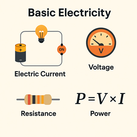
  • The concept of voltage is central to how electricity flows, as it represents the electrical pressure that pushes electrons through a circuit.

  • Understanding alternating current is essential, as it's the form of electricity most commonly delivered to homes and businesses.


Atomic Structure and the Nature of Electric Charge

If you can picture an atom as a sphere, imagine in the nucleus, in the centre, that contains at least one proton and at least one neutron. The proton is positively charged. In orbit around the nucleus is at least one electron, which is negatively charged. The reason they have these opposite charges takes us deep into the realm of quantum physics. We know that the neutron is made up of quarks and the electron is an elementary particle (it is not made up of anything and is a particle in its own right), but the reason why they have opposite charges is a matter beyond my meagre capabilities and, in any case, this area is at the fringes of human knowledge.


Electron Movement and Free Charge in Conductive Materials

Atoms may contain several protons and electrons. This variation is what distinguishes one element from another. Although described as sub-atomic particles, electrons have the properties of both particles and waves when it comes to fields of magnetism in electric circuits. In theory, at least, they could be both at the same time. If you want to know what materials conduct electricity well, see our overview of conductors, which explains how they allow electrons to move freely.

If an atom has no electric charge, i.e. it is neutral, then it contains the same number of protons as electrons. In some materials, most notably metals, the electrons' orbits around the nucleus are quite loose, allowing them to spin away from the atom. When this happens, the atom becomes positively charged because protons are in the majority within the atom. A free electron can join another atom. When this occurs, then the new host atom becomes negatively charged because the electrons are in the majority (assuming the atom was neutral in the first place). Devices like ammeters and multimeters are essential for measuring electrical current and diagnosing circuit performance.


Potential Difference and the Creation of Electric Current

There are many views about the subject. If you ask science experts on YouTube to show how static electricity works, they will report that opposites attract. The greater the difference between the number of electrons and protons, the greater the attraction will be. This is called a potential difference. If we can therefore manage to produce a negative charge at one end of a copper wire and a positive charge at the other end, free electrons would move towards the positive end. As electrons leave those atoms nearest the positive end, they leave behind positively charged atoms. Electrons from neighbouring atoms will be attracted towards these positive atoms, thus creating yet more positive atoms in their wake. This continuing transfer of electrons is called current. The greater the potential difference, or voltage, measured in its unit, the greater the force of the flow of electrons, or current.


Understanding Direct and Alternating Current (DC vs AC)

Electric power can be supplied as direct current (e.g. from car batteries for lighting) or as alternating current (e.g. household mains). To explore the differences between current types, read our guide on the difference between AC and DC, which explains why each type is used in different applications.


How Transformers Adjust Voltage for Power Distribution

Often, an electrical product requires a different voltage from the one supplied by the mains electric power. In these cases, a transformer rating is required. The use of transformers is very common along power lines and in electrical devices. In addition to the step-up transformers that increase voltage, transformers can also reduce voltage. These step-down transformers can be found at utility substations where the very high voltages required to push electrons through long transmission wires are reduced for local consumption.


Related Articles


Related News

What is a Busbar?

A busbar is a metallic strip or bar used in electrical systems to conduct electricity within switchgear, distribution panels, and substations. It distributes power efficiently and reduces resistance, enhancing safety and electrical performance.


What is a Busbar?

A busbar is a crucial electrical component used to conduct, distribute, and manage power in electrical systems. Found in commercial, industrial, and utility applications, it helps centralize connections and minimize wiring complexity.

✅ Provides efficient power distribution in electrical panels and substations

✅ Reduces resistance and improves system reliability

✅ Supports compact, organized electrical design for switchgear and distribution boards

A Busbar is an important component of electrical distribution systems, providing a central location for power to be distributed to multiple devices. It is an electrical conductor responsible for collecting electrical power from incoming feeders and distributing it to outgoing feeders. They are made of metal bars or metallic strips and have a large surface area to handle high currents.

How Does it Work?

It is a strip or bar made of copper, aluminum, or another conductive metal used to distribute electrical power in electrical systems. They have a large surface area to handle high currents, which reduces the current density and minimizes losses. They can be insulated or non-insulated, and they can be supported on insulators or wrapped in insulation. They are protected from accidental contact by either a metal earthed enclosure or elevation out of normal reach.

They collect electrical power from incoming feeders and distribute it to outgoing feeders. The bus bar system provides a common electrical junction for various types of electrical equipment, designed to handle high currents with minimal losses. They are often used in industrial applications, where they are installed in electrical panels or switchgear panels.


Different Types of Busbars

Different types of busbars are available on the market, including those made of copper or aluminum, as well as insulated or non-insulated, and segmented or solid busbars. Copper or brass busbars are used in low-voltage applications, while aluminum busbars are used in high-voltage applications. Insulated busbars are used in situations where accidental contact can occur, and segmented busbars are used to connect different types of equipment.

Busbars can also be classified based on their cross-section. A rectangular is the most common type and is often used in low-voltage applications. On the other hand, a tubular busbar is a hollow cylinder used in high-voltage applications. Finally, a circular one has a circular cross-section and is used in high-current applications.


Busbar Types and Characteristics

Attribute Copper Busbar Aluminum Busbar Laminated Busbar
Conductivity Excellent (≈100% IACS) Good (≈61% IACS) Varies (depends on internal conductor materials)
Weight Heavy Lightweight Moderate
Cost Higher Lower Higher (due to fabrication complexity)
Heat Dissipation Excellent Good Excellent (designed to reduce hot spots)
Applications Switchgear, substations, panels Bus ducts, high-rise buildings Compact power modules, UPS, power electronics
Mechanical Strength High Moderate Moderate to High
Corrosion Resistance High (especially tinned copper) Requires anodizing/coating Depends on encapsulation
Ease of Fabrication Good Excellent Complex


The Purpose of a Busbar in an Electrical System

The primary purpose of an electrical system is to distribute electrical power to different parts of the system. The busbar system collects electrical power from incoming feeders and distributes it to outgoing feeders. Busbars also provide a common electrical junction for different types of electrical equipment.


Busbar and Circuit Breakers

They are often used in conjunction with circuit breakers. Circuit breakers protect electrical circuits from damage caused by overload or short circuits. Additionally, they can be used to isolate the electrical supply in the event of a fault or overload. Circuit breakers are often installed in electrical or switchgear panels, which can be easily accessed and maintained.


Busbars and Electrical Distribution Equipment

They are an essential component of electrical distribution equipment, including electrical panels, switchgear panels, and distribution boards. Electrical panels distribute power to various parts of a building, while switchgear panels control the flow of electrical power in industrial applications. Distribution boards divide the electrical supply into separate circuits at a single location.


Busbar Installation

Installing a busbar involves several basic steps. First, the busbar system's design must be created, considering both the electrical load and the required current-carrying capacity. Then, it is installed in the electrical panel or switchgear panel. Finally, it is connected to the electrical equipment using either bolts, clamps, or welding.


Maintenance

Maintaining a busbar system involves regular inspections and cleaning. The system should be inspected for any damage or corrosion, and the connections should be tightened if they become loose. Regular cleaning of the system is also essential to prevent the buildup of dust or dirt, which can lead to a short circuit.


Safety Precautions

Working with busbars involves high voltage and current, so taking proper safety precautions is essential. The system must be isolated from the electrical system before any maintenance is performed. Personal protective equipment, such as gloves and safety glasses, should be worn while working with busbars. Working on a live system should only be done by trained personnel after ensuring that all necessary safety precautions are in place.


Accidents involving Busbars

Accidents can occur when working with busbars, and they can be dangerous if proper safety precautions are not taken. One common accident that can occur involves accidental contact with a live one. This can cause electrical shock, burns, and even death. Another accident involves short circuits, which can lead to equipment damage, fire, or explosions. These accidents can be prevented by following proper safety procedures and wearing personal protective equipment.

Arc flash accidents, including busbars, are a potential hazard when working with electrical equipment. An arc flash is an electrical explosion that can occur when a fault occurs in an electrical circuit, resulting in a short circuit or electrical discharge. Arc flash accidents can cause severe burns, hearing loss, and even death.

They can be a source of arc flash accidents if proper safety precautions are not taken. For example, if a live busbar comes into contact with an object, it can cause an arc flash. Proper insulation and guarding are necessary to prevent arc flash accidents involving busbars. They should also be installed in a way that minimizes the possibility of accidental contact.

Additionally, they should be designed to handle the expected current load, as overloading can lead to a fault and an arc flash. It is also essential to follow proper maintenance procedures, including regular system inspections and cleaning, to prevent damage or corrosion that can cause faults and arc flashes.

Overall, busbars are related to arc flash accidents as they can be a source of electrical faults that can lead to an arc flash. Therefore, following proper safety procedures, including proper insulation, guarding, and system maintenance, is crucial to prevent arc flash accidents.


Related Articles


View more

What is Electricity?

Electricity is the flow of electric charge, usually through a conductor like wire. It powers lights, appliances, and machines by converting energy into motion, heat, or light. Electricity can be generated from sources such as fossil fuels, wind, solar, or water.


What is electricity?

Electricity is a fundamental form of energy created by the movement of electrons.

✅ Powers homes, industries, and electronic devices

✅ Flows through circuits as an electric current

✅ Generated from renewable and non-renewable sources

The power we use is a secondary energy source because it is produced by converting primary energy sources such as coal, natural gas, nuclear, solar, and wind energy into electrical power. It is also referred to as an energy carrier, meaning it can be converted into other forms of energy, such as mechanical or thermal energy.

Primary energy sources are either renewable or nonrenewable, but our power is neither.

To understand why electrons move in the first place, start with voltage, the electrical “pressure” that pushes charge through every circuit.


Electricity Has Changed Everyday Life

Although most people rarely think about electricity, it has profoundly changed how we live. It is as essential as air or water, yet we tend to take it for granted—until it’s gone. Electricity powers heating and cooling systems, appliances, communications, entertainment, and modern conveniences that past generations never imagined.

Before widespread electrification began just over a century ago, homes were lit with candles or oil lamps, food was cooled with ice blocks, and heating was provided by wood- or coal-burning stoves.

The steady stream of electrons we use daily is explored in our primer on current electricity.


Discovering Electricity: From Curiosity to Power Grid

Scientists and inventors began unlocking the secrets of electricity as early as the 1600s. Over the next few centuries, their discoveries built the foundation for the electric age.

Benjamin Franklin demonstrated that lightning is a form of electricity.

Thomas Edison invented the first commercially viable incandescent light bulb.

Nikola Tesla pioneered the use of alternating current (AC), which enabled the efficient transmission of electricity over long distances. He also experimented with wireless electricity.

Curious why Tesla’s ideas beat Edison’s? Our article on alternating current breaks down the advantages of alternating current (AC) over direct current (DC).

Before Tesla’s innovations, arc lighting used direct current (DC) but was limited to outdoor and short-range applications. His work made it possible for electricity to be transmitted to homes and factories, revolutionizing lighting and industry.


Understanding Electric Charge and Current

Electricity is the movement of electrically charged particles, typically electrons. These particles can move either statically, as in a buildup of charge, or dynamically, as in a flowing current.

All matter is made of atoms, and each atom consists of a nucleus with positively charged protons and neutral neutrons, surrounded by negatively charged electrons. Usually, the number of protons and electrons is balanced. But when that balance is disturbed—when electrons are gained or lost—an electric current is formed as those electrons move.

For a step-by-step walkthrough of everything from circuits to safety, visit how electricity works.


Electricity as a Secondary Energy Source

Electricity doesn’t occur naturally in a usable form. It must be generated by converting other types of energy. In fact, electricity is a manufactured product. That’s why electricity is called a secondary energy source—it carries energy from its original form to where we need it.

We generate electricity by transforming mechanical energy—such as spinning a turbine—into electrical energy. This conversion happens at power plants that use a variety of fuels and methods:

  • Fossil fuels (coal, oil, natural gas)

  • Nuclear energy

  • Renewable sources like wind, solar, and hydroelectric

If turbines, magnets, and power plants intrigue you, see how electricity is generated for a deeper dive.


How Electricity Was Brought Into Homes

Before electricity generation began on a mass scale, cities often developed near waterfalls, where water wheels powered mills and machines. The leap from mechanical energy to electrical energy enabled power to travel not just across a town, but across entire countries.

Beginning with Franklin’s experiments and followed by Edison’s breakthrough with indoor electric light, the practical uses of electricity expanded rapidly. Tesla’s AC power system made widespread electric distribution feasible, bringing light, heat, and industry to homes and cities worldwide.


How Transformers Changed Everything

To transmit electricity efficiently over long distances, George Westinghouse developed the transformer. This device adjusts the voltage of electrical power to match its purpose—high for long-range travel, low for safe use in homes.

Transformers made it possible to supply electricity to homes and businesses far from power plants. The electric grid became a coordinated system of generation, transmission, distribution, and regulation.

Even today, most of us rarely consider the complexity behind our wall sockets. But behind every outlet lies a vast infrastructure keeping electricity flowing safely and reliably.


How Is Electricity Generated?

Electric generators convert mechanical energy into electricity using the principles of magnetism. When a conductor—such as a coil of wire—moves through a magnetic field, an electric current is induced.

In large power stations, turbines spin magnets inside massive generators. These turbines are driven by steam, water, or wind. The rotating magnet induces small currents in the coils of wire, which combine into a single continuous flow of electric power.

Discover the principle that turns motion into power in electromagnetic induction, the heart of every modern generator.


Measuring Electricity

Electricity is measured in precise units. The amount of power being used or generated is expressed in watts (W), named after inventor James Watt.

  • One watt is a small unit of power; 1,000 watts equal one kilowatt (kW).

  • Energy use over time is measured in kilowatt-hours (kWh).

  • A 100-watt bulb burning for 10 hours uses 1 kWh of electricity.

These units are what you see on your electric bill. They represent how much electricity you’ve consumed over time—and how much you’ll pay.

When it’s time to decode your energy bill, the chart in electrical units makes watts, volts, and amps clear.


Related Articles


View more

What is a Potentiometer?

A potentiometer is a variable resistor that adjusts voltage in a circuit. It’s used for controlling electrical devices like volume knobs, sensors, and dimmers. Potentiometers regulate current flow by varying resistance, making them essential in analog electronic applications.


What is a Potentiometer?

A potentiometer is a type of adjustable resistor used to control voltage or current in an electrical circuit.

✅ Adjusts resistance to control voltage in circuits

✅ Commonly used in audio controls and sensors

✅ Essential for analog signal tuning and regulation

At its core, a potentiometer functions as a variable resistor. By moving the wiper (a movable terminal) across a resistive element, the device varies the output voltage. Depending on the position of the wiper, varying amounts of resistance are introduced into the circuit, thereby adjusting the current flow.

When the wiper moves along the resistive track, it adjusts the total resistance in the circuit, which controls the flow of current. To learn more, see our guide on Electrical Resistance.

A potentiometer acts as an adjustable Voltage divider, splitting the input voltage proportionally between two output terminals based on the wiper’s position.

This relationship is governed by Ohm’s Law Formula, which states that voltage equals current multiplied by resistance (V = IR).

As shown in Figure 6-8, the basic construction of a potentiometer includes:

  • A resistive track (usually carbon, cermet, or wire wound)

  • A movable wiper

  • Three terminals (two fixed, one connected to the wiper)

This setup enables the potentiometer to function as both a voltage divider and a simple variable resistor.


Fig. 6-8 Construction geometry of a potentiometer


Types of Potentiometers

Potentiometers come in several forms, each designed for specific applications:

A potentiometer is considered a variable resistor, one of several important types covered in our guide to Types of Resistors.


Rotary Potentiometer

The most common type, rotary potentiometers, adjust resistance through the rotation of a knob. These are frequently found in volume controls, light dimmers, and measuring instruments. The resistive track inside a potentiometer is made from materials that partially conduct electricity, such as carbon or cermet. For more on conductive materials, see Conductor of Electricity.


Figure 6-9 illustrates the typical circuit symbol for a rotary potentiometer.


Linear Potentiometer (Slide Potentiometer)

Instead of rotating, a linear potentiometer, often referred to as a slide potentiometer, adjusts by sliding a control lever. These are widely used in audio mixers and precision instruments where fine, linear adjustments are needed.


Audio Taper Potentiometer

In audio equipment, human hearing sensitivity is non-linear. Audio taper potentiometers adjust resistance logarithmically to provide a natural, smooth volume change that matches human perception.

Note: If you use a linear-taper potentiometer for audio volume control, the sound may seem to jump suddenly instead of increasing smoothly.


Digital Potentiometer

Digital potentiometers, also known as "digipots," are electronically controlled rather than manually adjusted. They find use in automatic tuning circuits, programmable amplifiers, and microcontroller applications.


Rheostat (Variable Resistor)

Although technically a type of potentiometer, a rheostat uses only two terminals: one fixed terminal and the wiper. It is optimized to control current rather than voltage. Rheostats are commonly used in applications like motor speed control and light dimming.


Practical Applications of Potentiometers

Potentiometers are found in a wide range of everyday and industrial applications:

  • Audio Equipment: Volume and tone controls on stereos and guitars

  • Automobiles: Throttle position sensors, dashboard dimmers

  • Industrial Controls: Machinery speed adjustments

  • Consumer Electronics: Game controller joysticks

  • Laboratory Equipment: Calibration and fine adjustments

Potentiometers are versatile components used in both AC and DC electrical systems, from audio controls to automotive sensors.

Their ability to fine-tune voltage and resistance makes them essential in both analog and digital systems.


How to Test a Potentiometer

Testing a potentiometer is straightforward:

  1. Disconnect power to the circuit.

  2. Use a multimeter set to measure resistance (ohms).

  3. Connect the multimeter probes to the outer two terminals to measure total resistance.

  4. Measure between the wiper and one outer terminal; adjust the control and observe the changing resistance.

Consistent, smooth changes confirm proper operation. Jumps or dead spots may indicate a worn or faulty potentiometer.

A potentiometer is a simple but versatile component that provides adjustable control over voltage or resistance in a circuit. Whether used in audio systems, automotive sensors, or industrial machinery, its importance in electronic design and control systems is undeniable.

Understanding the various types and practical applications of potentiometers can help in selecting the appropriate device for a specific task.

For readers seeking a broader understanding of basic electrical principles, visit our overview of Electricity Fundamentals.


Frequently Asked Questions


What is the difference between a potentiometer and a rheostat?

A potentiometer typically acts as a voltage divider with three terminals, while a rheostat uses only two terminals to control current.


Where are potentiometers commonly used?

Potentiometers are used in volume controls, sensors, gaming controllers, industrial equipment, and calibration tools.


How does a potentiometer adjust voltage?

By moving the wiper across the resistive track, a potentiometer divides the input voltage proportionally between the two output terminals, adjusting the output voltage.


Related Articles


View more

What is Electric Load

Electric load refers to the amount of electrical power consumed by devices in a system. It determines demand on the power supply and affects energy distribution, efficiency, and system design.


What is Electric Load?

✅ Measures the power consumed by electrical devices or systems

✅ Impacts system design, energy use, and load management

✅ Varies by time, usage patterns, and connected equipment

What is electric load? It refers to the total power demand placed on a circuit by connected devices. Electric load, such as lighting, motors, and appliances, impacts energy use, system sizing, and overall efficiency across residential, commercial, and industrial settings.

An electric load refers to any device or system that consumes electric power to perform work, such as an electric motor, lighting fixture, or household electrical appliances. These loads draw electrical energy from the power source, impacting both system efficiency and capacity planning. Accurate electrical load calculation is crucial for designing circuits, selecting the correct breakers, and ensuring safe operation in homes, businesses, and industrial facilities. Using real-time monitoring tools, engineers can assess load patterns, identify peak demand, and implement energy-saving strategies through smart load management systems.

An electric load can be anything that consumes power, such as lights, appliances, heating systems, motors, and computers. In electrical engineering, a load represents the demand that a device or installation places on the power source.

Electric load is closely influenced by regional consumption patterns, which can be explored in more detail in Electricity Demand in Canada, highlighting how climate and industry shape national power usage.

Different types of types exist, and they are classified based on their characteristics. Resistive loads include, for example, converting energy directly into heat, such as heaters or incandescent light bulbs. Inductive loads, however, require energy to create a magnetic field, such as motors or transformers. Capacitive loads, meanwhile, store and release energy, such as capacitors used in a powered circuit.


An electric load refers to any device or circuit that consumes energy in a system. A common example is a load that consists of appliances such as heaters or ovens, where the primary component is a heating element. This heating element converts energy into heat, providing warmth or cooking power. It consists of a heating mechanism that demands specific amounts of powered energy depending on the device’s power requirements, which is crucial for maintaining an efficient and balanced system. For readers new to electrical concepts, the Basic Electricity Handbook provides foundational knowledge that helps contextualize the meaning of electricity in power systems.


Types of Electrical Loads

Electric loads fall into three primary categories:

  • Resistive: Devices like incandescent light bulbs, heaters, and toasters. These convert energy directly into heat.

  • Inductive: Motors, transformers, and fans. Inductive loads create magnetic fields to operate, often resulting in a lagging power factor.

  • Capacitive: Capacitors are used in power factor correction equipment or some specialized electronic devices. They store energy temporarily.

Each load type interacts differently with the system, impacting both efficiency and stability.

Related: Understand how resistive loads behave in a circuit.


How to Calculate Electric Load

Accurately calculating electric load is important for selecting the correct wire size, circuit breakers, and transformer ratings.


For example:

  • If a device operates at 120 volts and draws 5 amps:

    • Load = 120 × 5 = 600 watts


Step-by-Step Example for a Household Circuit:

  1. Add up the wattage of all devices on the circuit.

  2. Divide the total wattage by the system voltage to find the total current load.

  3. Compare the load to the circuit breaker rating to ensure it is not overloaded.

Tip: Always design for 80% of breaker capacity for safety.


Why Understanding Electric Load Matters

Understanding electric load has real-world implications:

  • Energy Bills: Higher demand results in higher costs, particularly for businesses subject to demand charges.

  • System Design: Correct assessment ensures that wiring, transformers, and protection devices are appropriately sized.

  • Power Quality: Poor management can lead to low power factor, voltage drops, and even system instability.

  • Maintenance Planning: Predictable loads extend the life of equipment and reduce costly downtime.


Management Strategies

Smart load management can improve system efficiency and reduce costs:

  • Peak Shaving: Reducing consumption during periods of high demand.

  • Shifting: Moving heavy loads to off-peak hours.

  • Power Factor Correction: Installing capacitors to improve system efficiency and lower bills.


Electric load is a critical concept in both residential and industrial settings. By understanding the types of calculations used to determine total demand and the practical impacts on energy costs and system design, you can build safer, more efficient systems.

One critical aspect is the power factor. Power factor is the ratio of active power (measured in watts) to apparent power (measured in volt-amperes). In simpler terms, it is the efficiency of energy usage. A low power factor indicates that a device or system consumes energy more than necessary to perform a given task, leading to higher energy costs and increased strain on the power grid. The relationship between load, bill, and motor is especially evident in provincial models, such as Ontario’s Electricity Cost Allocation, which explains how peak demand affects consumer rates.

An electric load is a critical concept in the design and operation of the power grid. Understanding how it is measured, the different types, power factor, management strategies, peak, shedding, and demand response programs are essential for optimizing the use of the grid and ensuring its reliability. By balancing the demand for power with the grid's capacity, we can reduce energy costs, prevent blackouts, and create a more sustainable energy system. Management is a critical component of infrastructure planning, as discussed in the Transmission & Distribution Channel, which examines how levels affect grid design and performance.

In industrial environments, managing efficiently can lead to significant cost savings and operational stability. Explore these strategies in the Industrial Electric Power Channel.


View more

What do Ammeters Measure?

An ammeter measures electric current in a circuit, displayed in amperes (A). Connected in series with low internal resistance to reduce burden voltage, it ensures accurate readings for testing, fault detection, and diagnostics.


What do Ammeters Measure?

Ammeters are measuring devices that measure the flow of electricity in the form of current in a circuit.

✅ Measure electric current in amperes, connected in series with low internal resistance to minimize burden voltage.

✅ Available in analog, digital, clamp, and current transformer designs.

✅ Used for testing, fault detection, continuity checks, and diagnostics.

Electrical currents are then measured in the form of amperes, hence the name "ammeter". The term "ammeter" is sometimes used incorrectly as "ampmeter". Understanding how an ammeter works is easier when you first explore the basics of electricity fundamentals, including how voltage, current, and resistance interact in a circuit.

An ammeter measures electric current in a circuit, expressed in amperes (A). It must be connected in series with the load so that all the current flows through it, and is designed with low internal resistance to minimize burden voltage, thereby ensuring accurate readings without significantly affecting the circuit’s performance. The measurement unit for an ammeter is the ampere, explained in detail on our what is an ampere page, which also covers its relationship to other electrical units.

Ammeters are designed (as well as ohmmeters and voltmeters) to be used with a sensitive current detector such as a moving coil in a galvanometer. To measure the electric current flow through it, an ammeter is placed in series with a circuit element. The ammeter is designed to offer very low resistance to the current, so that it does not appreciably change the circuit it is measuring. To do this, a small resistor is placed in parallel with the galvanometer to shunt most of the current around the galvanometer. Its value is chosen so that when the design current flows through the meter, it will deflect to its full-scale reading. A galvanometer's full-scale current is very small: on the order of milliamperes. To see how ammeters fit into broader measurement tools, check out our guide on what is a voltmeter and what is a multimeter, which measure multiple electrical properties.

An Ammeter is analog. It is not mechanical or digital. It uses an analog-to-digital converter (ADC) to measure the voltage across the shunt resistor. The ADC is read by a microcomputer that performs the calculations to display the current through the resistor.


How an Ammeter Works

An ammeter works by being placed in series with the circuit so that all the current flows through it. Inside, a shunt resistor with very low internal resistance creates a small, measurable voltage drop proportional to the current. In analog designs, this current is partly diverted around a sensitive moving-coil mechanism, which displays the reading on a scale. In digital designs, the voltage drop across the shunt is measured by an analog-to-digital converter (ADC) and calculated into an amperes value, ensuring accurate measurement without significantly disturbing the circuit’s performance. Accurate current measurement also depends on understanding what is electrical resistance and how it affects current flow, especially in low-resistance ammeter designs.


Types and Mechanisms

Analog ammeter – Includes moving-coil (D'Arsonval) and moving-iron types, which use magnetic deflection to display current on a scale. These designs are valued for their simplicity, durability, and ability to provide continuous current readings.

Digital ammeter – Uses a shunt resistor to create a small voltage drop proportional to the current. This voltage is measured by an analog-to-digital converter (ADC) and displayed as a precise digital value. Digital ammeters often feature higher accuracy, wider measurement ranges, and additional functions such as data logging.

Clamp meter – Measures current without breaking the circuit by detecting the magnetic field around a conductor. This method is ideal for quick testing, especially in high-current applications or where live connections cannot be interrupted.

Current transformer (CT) ammeter – Designed for high-current AC systems, this type uses a transformer to scale down large primary currents into a safe, measurable secondary current for the meter.


Shunts and Operation

A shunt resistor is a precision, low-resistance component used in many ammeters. In analog designs, it is placed in parallel with the meter movement, diverting most of the current to protect the instrument. In certain digital designs, it is placed in series with the circuit. By measuring the voltage drop across the shunt and applying Ohm’s law, the meter accurately calculates the current. This approach allows for measurement of very large currents without damaging the meter and helps maintain measurement stability.


Applications and Value

Ammeters are essential tools in electrical testing, short-circuit detection, continuity testing, and system diagnostics. They help identify overloads, open circuits, and unstable current conditions that may indicate equipment faults or inefficiencies.

In industrial, commercial, and residential settings, ammeters are used for equipment maintenance, troubleshooting, and performance monitoring. Specialized variants such as milliammeters and microammeters are designed for extremely low current measurements, while integrating ammeters track current over time to determine total electrical charge delivered to a device or system. For historical context on the development of measuring instruments, visit our history of electricity page to learn how electrical science evolved over time.


Practical Applications of Ammeters

Ammeters are used in a wide range of electrical and electronic work:

  • Automotive diagnostics – Measuring current draw from the battery to detect parasitic drains, starter motor issues, and charging system faults.

  • Solar panel and battery monitoring – Tracking current output from photovoltaic arrays and the charging/discharging rates of storage batteries to optimize system efficiency.

  • Industrial motor maintenance – Monitoring motor current to identify overload conditions, detect bearing wear, or confirm correct load operation.

  • Household appliance servicing – Checking current draw to troubleshoot faulty components or ensure devices operate within safe limits.

  • Power distribution systems – Ensuring current levels remain within capacity for cables, fuses, and protective devices.


Related Articles


View more

What is a Voltmeter?

What is a voltmeter? A voltmeter is an electrical measuring instrument used to determine voltage across circuit points. Common in electronics, engineering, and power systems, it ensures accuracy, safety, and efficiency when monitoring current and diagnosing electrical performance.


What is a Voltmeter?

A Voltmeter provides a method to accurately measure voltage, which is the difference in electric potential between two points in a circuit, without changing the voltage in that circuit. It is an instrument used for measuring voltage drop.

✅ Ensures accurate voltage measurement for safety and performance

✅ Used in electrical engineering, electronics, and power systems

✅ Helps diagnose faults and maintain efficient operation

Electrical current consists of a flow of charge carriers. Voltage, also known as electromotive force (EMF) or potential difference, manifests as "electrical pressure" that enables current to flow. Given an electric circuit under test with a constant resistance, the current through the circuit varies directly in proportion to the voltage across the circuit. A voltmeter measures potential difference, which directly relates to Ohm’s Law, the fundamental equation connecting voltage, current, and resistance in circuits.

A voltmeter can take many forms, from the classic analog voltmeter with a moving needle to modern instruments like the digital voltmeter (DVM) or the versatile digital multimeter. These tools are essential for measuring electrical values in electronic devices, enabling technicians to measure voltage, current, and resistance with precision and accuracy. While analog units provide quick visual feedback, digital versions deliver more precise measurements across wider voltage ranges, making them indispensable for troubleshooting and maintaining today’s complex electrical systems.

A voltmeter can be tailored to have various full-scale ranges by switching different values of resistance in series with the microammeter, as shown in Fig. 3-6. A voltmeter exhibits high internal resistance because the resistors have large ohmic values. The greater the supply voltage, the larger the internal resistance of the voltmeter because the necessary series resistance increases as the voltage increases. To understand how a voltmeter works, it helps to first review basic electricity, as voltage, current, and resistance form the foundation of all electrical measurements.


Fig 3-6. A simple circuit using a microammeter (tA) to measure DC voltage.


A Voltmeter, whether digital or analog, should have high resistance, and the higher the better. You don't want the meter to draw a lot of current from the power source. (Ideally, it wouldn't draw any current at all.) The power-supply current should go, as much as possible, towards operating whatever circuit or system you want to use, not into getting a meter to tell you the voltage. A voltmeter is commonly used to measure voltage drop across conductors or devices, helping electricians ensure circuits operate efficiently and safely. For quick calculations, a voltage drop calculator provides accurate estimates of conductor losses based on length, size, and current. Understanding the voltage drop formula allows engineers and technicians to apply theoretical principles when designing or troubleshooting electrical systems.

Also, you might not want to keep the voltmeter constantly connected in parallel in the circuit. You may need the voltmeter for testing various circuits. You don't want the behavior of a circuit to be affected the moment you connect or disconnect the voltmeter. The less current a voltmeter draws, the less it affects the behavior of anything that operates from the power supply. Engineers often ask: What is a voltmeter?  They use a voltmeter in power system analysis, where accurate voltage readings are crucial for ensuring safety, reliability, and optimal performance.

Alternative types of voltmeters use electrostatic deflection, rather than electromagnetic deflection, to produce their readings. Remember that electric fields produce forces, just as magnetic fields do. Therefore, a pair of electrically charged plates attracts or repels each other. An electrostatic type utilizes the attractive force between two plates with opposite electric charges or a large potential difference. A voltmeter is used to measure the potential difference. Figure 3-7 portrays the functional mechanics of an electrostatic meter. It constitutes, in effect, a sensitive, calibrated electroscope. A voltmeter draws essentially no current from the power supply. Nothing but air exists between the plates, and air constitutes a nearly perfect electrical insulator. A properly designed electrostatic meter can measure both AC voltage and DC voltage. However, the meter construction tends to be fragile, and mechanical vibration can influence the reading.


Fig 3-7. Functional drawing of an electrostatic voltmeter movement.


It's always good when a voltmeter has a high internal resistance. The reason for this is that you don't want the voltmeter to draw a significant amount of current from the power source. This cur­rent should go, as much as possible, towards working whatever circuit is hooked up to the supply, and not just into getting a reading of the voltage. Additionally, you may not want or need to have the voltmeter constantly connected in the circuit; instead, you might need it for testing various circuits. You don't want the behavior of the circuit to be affected the instant you connect the voltmeter to the supply. The less current a voltmeter draws, the less it will affect the behavior of anything that is working from the power supply.

If you connect an ammeter directly across a source of voltage, a battery, the meter needle will deflect. In fact, a milliammeter needle will probably be "pinned" if you do this with it, and a microammeter might well be wrecked by the force of the needle striking the pin at the top of the scale. For this reason, you should never connect milli-ammeters or micro-ammeters directly across voltage sources. An ammeter, perhaps with a range of 0-10 A, may not deflect to full scale if it is placed across a battery; however, it's still a bad idea to do so, as it will rapidly drain the battery. Some batteries, such as automotive lead-acid cells, can explode under these conditions. This is because all ammeters have low internal resistance. They are designed that way deliberately. They are meant to be connected in series with other parts of a circuit, not right across the power supply. Because voltage is inseparable from current, learning what is current electricity provides deeper insight into why voltmeters are vital diagnostic tools.

But if you place a large resistor in series with an ammeter, and then connect the ammeter across a battery or other type of power supply, you no longer have a short cir­cuit. The ammeter will give an indication that is directly proportional to the voltage of the supply. The smaller the full-scale reading of the ammeter, the larger the resistance needed to get a meaningful indication on the meter. Using a microammeter and a very large resistor in series, it can be devised that draws only a small current from the source.

So, What is a Voltmeter? In summary, a voltmeter is a fundamental instrument for electrical work, allowing professionals and students to accurately measure voltage and understand circuit behaviour. Whether using an analog or digital design, voltmeters and multimeters provide precise insights that support safety, efficiency, and reliable performance in electrical systems.

Related Articles


View more

Sign Up for Electricity Forum’s Newsletter

Stay informed with our FREE Newsletter — get the latest news, breakthrough technologies, and expert insights, delivered straight to your inbox.

Electricity Today T&D Magazine Subscribe for FREE

Stay informed with the latest T&D policies and technologies.
  • Timely insights from industry experts
  • Practical solutions T&D engineers
  • Free access to every issue

Download the 2025 Electrical Training Catalog

Explore 50+ live, expert-led electrical training courses –

  • Interactive
  • Flexible
  • CEU-cerified