What Is Static Electricity?
By R.W. Hurst, Editor
Static electricity is the accumulation of electrical charge on an object’s surface, usually from friction, induction, or contact. This imbalance of electrons and protons creates sparks, shocks, and attraction, influencing physics, electronics, and everyday energy phenomena.
What is Static Electricity?
Atoms also consist of positively charged particles called protons and neutral particles called neutrons. When an object gains or loses electrons, it becomes positively or negatively charged.
How Static Electricity Forms
Static electricity occurs when a static electric charge builds up on the surface of a material, often resulting from friction or the separation of objects. This phenomenon, commonly referred to as static, occurs when negative charges—specifically, electrons—accumulate in one area, creating an imbalance. When conditions allow, electrons jump suddenly to another surface to neutralize this difference, sometimes producing a visible spark or mild shock. Unlike materials that easily conduct, electrical insulators tend to trap these charges, making static buildup more likely.
Static electricity arises when there is an imbalance of charges, specifically, when electrons are transferred from one material to another. This can happen through two primary mechanisms: the triboelectric effect and electrostatic induction. To understand how electric charges interact in circuits, explore what is an electrical circuit and how current flow differs from static buildup.
Triboelectric Effect
When two different materials come into contact and then separate, electrons move from one surface to the other. The object that loses electrons becomes positively charged, and the one that gains them becomes negatively charged. This is the most common way static electricity is created.
-
Clothes sticking after being dried
-
A balloon clinging to a wall after rubbing on hair
Electrostatic Induction
Unlike the triboelectric effect, induction involves no direct contact. A charged object brought near a neutral object can cause electrons within the neutral object to shift positions, creating areas of opposite charge. This redistribution allows static electricity to form without touching. Since friction between insulating materials often generates static charge, it’s helpful to know what is a conductor and what is an insulator.
Conductors vs. Insulators
The behavior of static electricity largely depends on the type of material involved. Some materials allow charge to flow freely, while others trap it.
Insulators prevent the free movement of electrons, allowing charge to build up on their surfaces. Common insulators include rubber, plastic, and glass. Conductors, on the other hand, permit electrons to move easily, which helps dissipate static buildup. Metals like copper and aluminum are typical conductors. To understand how material properties affect charge buildup and dissipation, visit what is a conductor and what is electrical resistance.
-
Insulators hold static charge and are prone to build up
-
Conductors allow electrons to flow, preventing accumulation
-
Static electricity often forms between two insulating surfaces
Electrostatic Discharge (ESD)
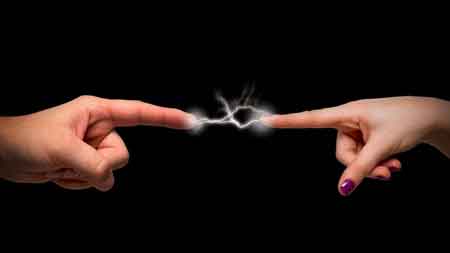
A sudden movement of static electricity from one object to another is known as electrostatic discharge, or ESD. This release can happen in a fraction of a second and may result in a visible spark or a mild electric shock.
Though often harmless in daily life, ESD can be hazardous in industrial settings. It can ignite flammable vapors or damage sensitive electronic components.
-
Shocks from doorknobs or car doors
-
Sparks in dry environments
-
Damage to circuit boards and microchips
This process is driven by a difference in electric potential. To explore this concept further, visit what is voltage.
The behavior of electrons in materials also relates to what is capacitance, a key concept in storing electrostatic energy.
Real-World Examples
Static electricity isn’t just theoretical—it manifests in many everyday situations, often in surprising or frustrating ways.
-
Static cling in laundry
-
Hair standing on end in dry air
-
A comb attracts small bits of paper
-
Lightning storms—giant-scale electrostatic discharge
How to Prevent Static Electricity
Managing it, especially in dry environments or around sensitive equipment, is essential. Thankfully, there are several simple and effective insulator materials to reduce static buildup at home or in the workplace.
-
Use humidifiers to increase air moisture
-
Apply antistatic sprays to fabrics and carpets
-
Wear natural fibers instead of synthetics
-
Touch grounded metal before handling electronics
-
Use antistatic wristbands or grounding mats when working on computers
Preventing shocks is part of general electrical safety, see dangers of electricity for more on how electrostatic discharge fits into the broader picture of electrical hazards.
Differences Between Static and Current Electricity
Although both involve electric charge, static electricity and current electricity behave very differently. Understanding the contrast helps explain why one causes shocks and the other powers devices.
| Feature | Static Electricity | Current Electricity |
|---|---|---|
| Charge Movement | Stationary | Flows through a conductor |
| Source | Friction or induction | Battery, generator, power source |
| Use in Devices | Limited | Essential for powering devices |
To better understand flowing charge and how it contrasts with static buildup, visit what is current electricity.
Applications of Static Electricity
Electrostatic force is more than a nuisance — it has practical applications across several industries. Scientists and engineers use electrostatic principles to solve real-world problems and improve everyday technologies.
-
Electrostatic precipitators filter pollutants from factory exhaust
-
Laser printers and copiers use static charge to transfer toner
-
Paint sprayers evenly coat surfaces using electrostatic attraction
-
Electrostatic generators like the Van de Graaff produce high voltages for demonstrations and research
Demonstrating Static Electricity
You don’t need a lab to see the electrostatic force in action. Simple household materials can illustrate how this invisible force works.
-
Rubbing a balloon on your hair and sticking it to a wall
-
Combing dry hair and attracting paper pieces
-
Using a Van de Graaff generator to make hair stand on end
The electrostatic force is the force that holds these positive and negative charges together or pushes them apart. When two objects come into contact, the triboelectric effect can transfer electrons from one object to the other. This causes both objects to become charged, with one gaining electrons and becoming negatively charged and the other losing electrons and becoming positively charged.


Insulators and conductors play a crucial role. Insulators are materials that do not allow extra electrons to flow freely, such as rubber, plastic, or glass. Conductors, on the other hand, are materials like metals that easily enable electrons to flow. When two insulators come into contact, they are more likely to generate a static charge, as electrons cannot easily move between them.
Frequently Asked Questions
What causes static electricity?
It’s caused by either the triboelectric effect (contact and separation) or electrostatic induction (non-contact charge redistribution).
What is electrostatic induction?
It’s when a nearby charged object causes the electrons in another object to shift, without any physical contact.
Why does it cause shocks?
Because the excess charge seeks to neutralize, jumping to a grounded object like your body, creating a quick discharge.
Is it dangerous?
Yes, in some cases. It can ignite flammable gases or damage delicate electronics through electrostatic discharge.
How can I prevent static buildup at home?
Keep humidity levels up, avoid synthetic materials, and use grounding methods like touching metal before contact.
What are industrial safety measures?
Professionals use ESD-safe tools such as antistatic wristbands, mats, and ionizing blowers to prevent damage and injury.
As we've explored, electrostatic charge imbalance is an intriguing and complex phenomenon influencing various aspects of our lives. From the simple yet surprising instances of hair standing on end to the practical applications in industries, understanding and harnessing this force can open up new possibilities in science, technology, and even our daily routines. By continuing to study and explore static electricity, we can unlock its full potential and utilize it to enhance our lives in numerous ways, making them better and more efficient.
It is a captivating subject that permeates our lives in various ways. By understanding the science behind it, we can better appreciate its effects, take precautions to avoid potential hazards, and explore its myriad applications in technology and industry. Moreover, as we continue to learn more about this invisible force, we can undoubtedly find new ways to harness and utilize it in our everyday lives and beyond.
Related Articles
