What is a Potentiometer?
By Howard Williams, Technical Editor
A potentiometer is a variable resistor used to control voltage and signal levels in electronic circuits. It adjusts resistance through a movable wiper and is commonly used in audio controls, sensors, dimmers, and calibration applications.
What is a Potentiometer?
What is a potentiometer? A potentiometer is a variable resistor used to control voltage and signal levels in electronic circuits. It adjusts resistance through a movable wiper and is commonly used in audio controls, sensors, dimmers, and calibration applications.
What tends to surprise people new to electronics is how often potentiometers show up in places that feel intuitive rather than technical. A volume knob, a dimmer slider, or a joystick does not announce itself as a precision electrical component, yet each relies on the same simple idea. Change resistance, and the circuit responds.
At its core, a potentiometer functions as a variable resistor, but the way it is used matters. As the internal wiper moves across the resistive element, it changes the amount of input voltage available at the output. That motion translates directly into control, whether it is softening a guitar signal, fine-tuning a sensor, or trimming a reference voltage during calibration.
When the wiper shifts position, resistance changes smoothly rather than abruptly. That gradual change is what makes potentiometers useful for human-operated controls. To learn more, see our guide on Electrical Resistance. The underlying behaviour follows the same relationship described by Ohm’s Law Formula, in which voltage, current, and resistance are tightly linked. Still, the experience of using one feels analog and continuous rather than binary.
A potentiometer can also act as a Voltage divider. Instead of simply limiting current, it proportionally splits the input voltage between two points, with the output determined by the wiper position. This is why potentiometers appear so often in signal-level applications rather than in power-delivery applications.
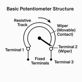
Physically, the construction is straightforward. A resistive track, commonly carbon, cermet, or wire-wound material, forms a path between two fixed terminals. A third terminal connects to the wiper, which slides or rotates along that path. The simplicity of this geometry is part of its longevity. There are a few components that can fail, and when wear does occur, the symptoms are usually easy to diagnose.
As shown in Figure 6-8, the basic construction of a potentiometer includes:
-
A resistive track (usually carbon, cermet, or wire wound)
-
A movable wiper
-
Three terminals (two fixed, one connected to the wiper)
This setup enables the potentiometer to function as both a voltage divider and a simple variable resistor.
Fig. 6-8 Construction geometry of a potentiometer
When voltage is applied across a potentiometer, the way its output responds depends largely on the potentiometer's internal design. A device with a linear taper changes variable resistance at a steady rate as the knob turns, which is useful when predictable adjustment is needed. By contrast, a logarithmic taper follows a curve that better matches human perception, especially in audio applications. In situations where very fine adjustment is required, a multi-turn control allows small, precise changes that would be difficult to achieve with a single rotation.
Types of Potentiometers
What is a potentiometer, and what are the types? Potentiometers are not interchangeable by default. The way resistance changes relative to movement, and the form factor itself, can dramatically affect how a circuit behaves. These types are covered in our guide to Types of Resistors.
Rotary Potentiometer
The rotary potentiometer is the form most people recognize. Turning a knob rotates the wiper along a circular resistive track. These are common in audio equipment, lighting controls, and test instruments. In practice, rotary pots are favored when users expect tactile feedback and a defined range of motion. The resistive materials used inside are chosen for stability and wear characteristics, not just conductivity. For more on conductive materials, see Conductor of Electricity.
Figure 6-9 illustrates the typical circuit symbol for a rotary potentiometer.
Linear Potentiometer (Slide Potentiometer)
A linear, or slide, potentiometer replaces rotation with straight-line movement. Audio mixers are a familiar example, but linear pots also appear in measurement systems where position directly maps to output voltage. Engineers often choose them when visual alignment matters, because the control position can be read at a glance.
Audio Taper Potentiometer
Human hearing does not respond linearly to changes in signal level, and this is where audio taper potentiometers come into play; their resistance changes logarithmically, matching how volume is perceived rather than how voltage changes mathematically. Anyone who has tried to use a linear potentiometer for volume control has experienced the result: most of the audible change occurs in a small part of its rotation, which feels unnatural.
Digital Potentiometer
Digital potentiometers move the adjustment mechanism entirely out of the user’s hands. Instead of a physical wiper, internal switching networks adjust resistance electronically under microcontroller control. These devices are used where repeatability, remote adjustment, or automation is required, such as programmable amplifiers or self-calibrating systems.
Rheostat (Variable Resistor)
A rheostat is closely related to a potentiometer but typically has only two terminals. Rather than dividing voltage, it is intended to control current directly. Rheostats are designed to handle higher power levels and are often used in motor control and load-testing applications. While the internal principle is similar, the use case is distinctly different.
Practical Applications of Potentiometers
Potentiometers appear in far more systems than most people realize. In audio equipment, they shape tone and volume. In vehicles, they report throttle position and adjust dashboard lighting. Industrial machines rely on them for speed control and setpoint adjustment, while laboratory equipment uses them for precise calibration.

What is a potentiometer, and what makes potentiometers particularly valuable? It is their ability to bridge human input and electrical behavior. A small mechanical movement becomes a predictable electrical change, and that translation remains useful in both analog and digitally controlled systems. Potentiometers are versatile components used in both AC and DC electrical systems, from audio controls to automotive sensors. Their ability to fine-tune voltage and resistance makes them essential in both analog and digital systems.
How to Test a Potentiometer
Testing a potentiometer rarely requires specialized tools. With power removed, a standard multimeter set to measure resistance can reveal most faults. Measuring across the outer terminals confirms the total resistance, while measuring between the wiper and one end shows whether resistance changes smoothly as the control moves.
In practice, worn potentiometers announce themselves clearly. Sudden jumps, dead spots, or noisy readings usually indicate physical wear on the resistive track or contamination inside the housing. These issues tend to worsen over time rather than resolve on their own.
A potentiometer is a simple component, but its usefulness lies in its ability to translate motion into control reliably. From audio systems to industrial machinery, it remains one of the most practical tools for adjusting voltage and resistance in a circuit. For readers seeking a broader understanding of basic electrical principles, visit our overview of Electricity Fundamentals.
Frequently Asked Questions
What is a potentiometer and how does it control voltage?
A potentiometer is a variable resistor that controls voltage in a circuit by dividing the applied voltage based on the position of its movable wiper, allowing smooth adjustment of the output level.
What is the difference between a potentiometer and a rheostat?
A potentiometer typically uses three terminals and functions as a voltage divider, while a rheostat uses two terminals and is intended to control current.
Where are potentiometers commonly used?
They are found in audio controls, sensors, gaming controllers, industrial equipment, and calibration systems.
How does a potentiometer adjust voltage?
By moving the wiper along the resistive track, the device changes how input voltage is divided between the output terminals.
Related Articles

